
Method for enhancing lateral stiffness of multi-walled nanotube device by irradiation of electron beam

A technology of multi-walled nanotubes and electron beam irradiation, applied in the field of field emission nanotube devices, can solve problems such as nanotube probes with large lateral stiffness, and achieve the effects of good strength, good flexibility, and enhanced stiffness

Inactive Publication Date: 2011-05-18
TIANJIN UNIV
View PDF1 Cites 0 Cited by
  • Summary
  • Abstract
  • Description
  • Claims
  • Application Information

AI Technical Summary

Problems solved by technology

However, the preparation of nanotube probes with large aspect ratio and large lateral stiffness is still an unsolved manufacturing problem at home and abroad.

Method used

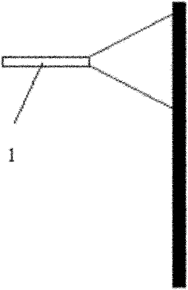

Image

  • Method for enhancing lateral stiffness of multi-walled nanotube device by irradiation of electron beam
  • Method for enhancing lateral stiffness of multi-walled nanotube device by irradiation of electron beam
  • Method for enhancing lateral stiffness of multi-walled nanotube device by irradiation of electron beam

Examples


Embodiment 1

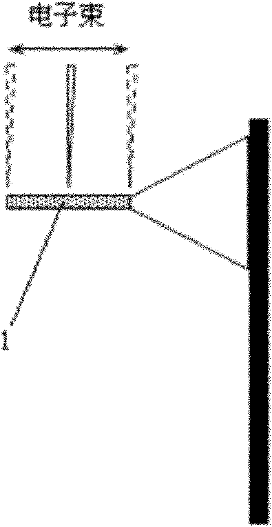
[0016] The basic principle diagram of embodiment 1 is shown in figure 2 : Use the same electron beam irradiation parameters to irradiate the nanotubes of the nanotube device as a whole, and 1 in the figure represents the multi-walled nanotubes whose overall stiffness is optimized after irradiation;

Embodiment 2

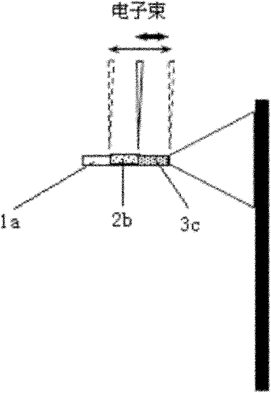
[0017] The basic principle diagram of embodiment 2 is shown in image 3 : Different electron beam irradiation parameters are used to irradiate different parts of the nanotube device. For the nanotube part of the nanotube device near the free end, that is image 3 In 1b, the electron beam with small beam current (100pA~1000pA) and low accelerating voltage (1kV~5kV) is used to irradiate it for 10s, and the irradiation intensity is reduced to ensure that the nanotube has good flexibility at this position; while in The position of the nanotube away from the dangling end and close to the substrate, that is, image 3 In 1c, the electron beam with large beam current (1nA~10nA) and high accelerating voltage (5kV~30kV) is used to irradiate it for 30s to increase the number of chemical bonds between layers and achieve the purpose of enhancing its stiffness;

[0018] 4. After reaching the expected parameters, stop the electron beam irradiation.


PUM


Abstract

The invention belongs to the technical field of feature detection and nanometer machining, and relates to a method for enhancing the lateral stiffness of a multi-walled nanotube device by the irradiation of an electron beam. The method comprises the following steps of: putting a suspended multi-walled nanotube device which needs stiffness optimization on a sample platform of focusing electron beam equipment, and regulating a multi-walled nanotube to be in the vertical direction of the electron beam; observing the feature of the multi-walled nanotube device by an electron beam imaging system, and adjusting the operating distance of the focusing electron beam; and changing different irradiation parameters of the electron beam, namely controlling the irradiation area, beam intensity, accelerating voltage and irradiation time parameters of the electron beam, opening a focusing electron beam generator, and performing the scanning irradiation of the electron beams on part of or all multi-walled nanotube of the suspended multi-walled nanotube device so as to meet the requirements on stiffness and flexibility. The method is stable and reliable, can realize later stiffness control over different structural characteristics of the suspended nanotube device, and has high positioning accuracy and flexibility.

Description

technical field [0001] The invention relates to a method for enhancing the lateral rigidity of a suspended nanotube device, which can be used in the fields of scanning probe microscope carbon nanotube probes in shape detection, nano processing, field emission nanotube devices and the like. Background technique [0002] The scanning probe microscope carbon nanotube probe is to fix the nanotube at the end of the ordinary probe, and use the carbon nanotube as the probe to work. Carbon nanotube probes have shown many excellent properties that ordinary probes do not have, such as higher resolution, wear resistance, and good flexibility. Due to the large aspect ratio, carbon nanotube probes are expected to be ideal probes for characterizing steep samples. However, due to the slender carbon nanotubes, the transverse elastic coefficient of the nanotube probe is small, which makes it easy to cause bending instability due to the small transverse stiffness when characterizing the morp...

Claims


Application Information

Patent Timeline
Patent Type & Authority Applications(China)
IPC IPC(8): B81C1/00
Inventor 徐宗伟房丰洲高海峰
Owner TIANJIN UNIV
Learn More