
Power supply device for grid-control electron gun, electron gun system and power supply method

A technology of gate-controlled electron guns and electrical devices, which is applied in the direction of cathode ray/electron beam tube electron guns, electrical components, electrode devices and related components, etc., can solve the problems of not being equal, and achieve less segment number, good stability, and beam current strong effect

Active Publication Date: 2021-03-30
INST OF MODERN PHYSICS CHINESE ACADEMY OF SCI
View PDF6 Cites 0 Cited by
  • Summary
  • Abstract
  • Description
  • Claims
  • Application Information

AI Technical Summary

Problems solved by technology

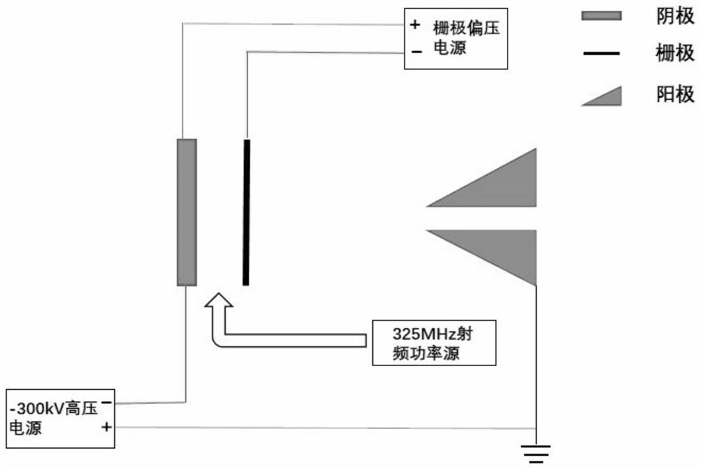
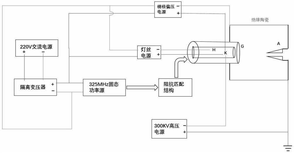
[0004]At present, in the field of microwave gate control, there are mainly the following problems: when microwaves are fed into the space between the cathode and grids, the structure will be closed, how to transmit microwaves Connecting each DC voltage to the inside of the cathode requires a detailed and reasonable plan
[0005] In addition, the coaxial power supply structure of the cathode of the electron gun may not be a standard 50 ohm device, which does not meet the matching conditions. It is necessary to design a specific transmission structure to complete impedance matching to ensure microwave Ability to efficiently feed between cathode and grid from a specific microwave power source

Method used


Image

  • Power supply device for grid-control electron gun, electron gun system and power supply method
  • Power supply device for grid-control electron gun, electron gun system and power supply method
  • Power supply device for grid-control electron gun, electron gun system and power supply method

Examples


Embodiment approach

[0105] One embodiment of the present invention is as follows: as Figure 5b As shown: the petal-shaped interface in front of port 2 is inserted into the coaxial base of the cathode, ports 2 to 6 are coaxial matching sections, and port 10 is a microwave injection interface. This interface can be a standard transmission line N-type female head structure. This section The corresponding impedance is 50Ω; the potentials between ports 7, 8, and 9 are independent, and are separated by an insulating member 600. Terminals are set at ports 7, 8, and 9, and the overlapping conductor structures set at ports 7 and 9 are as the first overlapping The conductor 801 and the second overlapping conductor 802 just close the second half of the microwave transmission (the right part in the figure), so that the microwave cannot continue to propagate in this direction. The coaxial inner diameter terminal 701 at the 7 port is connected to the left end of the first inner layer structure 200 through the...


PUM


Abstract

The invention relates to a power supply device for a grid-control electron gun, an electron gun system and a power supply method. The power supply device comprises a first outer-layer structure whichis a rotary conductor, wherein one end of the first outer-layer structure is provided with a grid interface, the other end is connected with a first power input interface, and a microwave input interface is arranged between the two ends; a first inner-layer structure which is a rotary conductor, wherein one end of the first inner-layer structure is provided with a cathode interface, and the otherend is connected with a second power input interface; and a second inner layer structure which is a rotary conductor, wherein one end is provided with a filament interface, and the other end is connected with a third power supply input interface. The first outer layer structure, the first inner layer structure and the second inner layer structure are coaxially arranged, the second inner layer structure is located on the innermost layer, and the first outer layer structure is arranged outside the first inner layer structure at intervals. The invention provides a dual-mode power supply device which meets the requirement of the electronic gun of the type for power supply during direct-current microwave use, the electronic gun system is designed and optimized, and a high-frequency beam bunch with higher quality can be obtained.

Description

technical field [0001] The invention relates to the technical field of electron linear accelerators, in particular to a power supply device for a gate-controlled electron gun, an electron gun system and a power supply method. Background technique [0002] A superconducting electron linear accelerator with high average current intensity, high average power and stable operation has very important applications in the fields of medicine and radiation. Because of the high atomic number, medical isotopes are mostly prepared by the reactor method. The early accelerators produced medical isotopes because the average beam current intensity and beam energy were low, resulting in extremely low production efficiency of isotopes and poor economic benefits, so they could not be put into industrial production. . In recent years, with the continuous development of superconducting technology, superconducting electron linear accelerators have made great progress. The high beam energy of this...

Claims


Application Information

Patent Timeline
Patent Type & Authority Applications(China)
IPC IPC(8): H01J29/48H05H7/22H05H9/00
CPCH01J29/485H05H9/00H05H7/22H01J2229/48
Inventor 夏乾旭张子民宗阳赵全堂曹树春申晓康李中平
Owner INST OF MODERN PHYSICS CHINESE ACADEMY OF SCI
Learn More