Fuel injector for an internal combustion engine

a fuel injector and internal combustion engine technology, applied in the direction of machines/engines, manufacturing tools, welding apparatus, etc., can solve the problems of unsatisfactory variation in the fuel flow rate, and achieve the effect of increasing the pintle stroke and avoiding such energy losses

Inactive Publication Date: 2010-01-21
DELPHI TECH INC
View PDF2 Cites 4 Cited by
  • Summary
  • Abstract
  • Description
  • Claims
  • Application Information

AI Technical Summary

Benefits of technology

[0010]By contrast, in a typical injector nozzle having a cylindrical metering region upstream of a tapered sealing portion, the flow area of the sealing band increases with increasing pintle stroke, causing the flow velocity to decrease and causing a loss of energy and af

Problems solved by technology

Furthermore, variation in the pintle stroke over time due to wear and/or differe

Method used


Image

  • Fuel injector for an internal combustion engine
  • Fuel injector for an internal combustion engine
  • Fuel injector for an internal combustion engine

Examples


Embodiment Construction

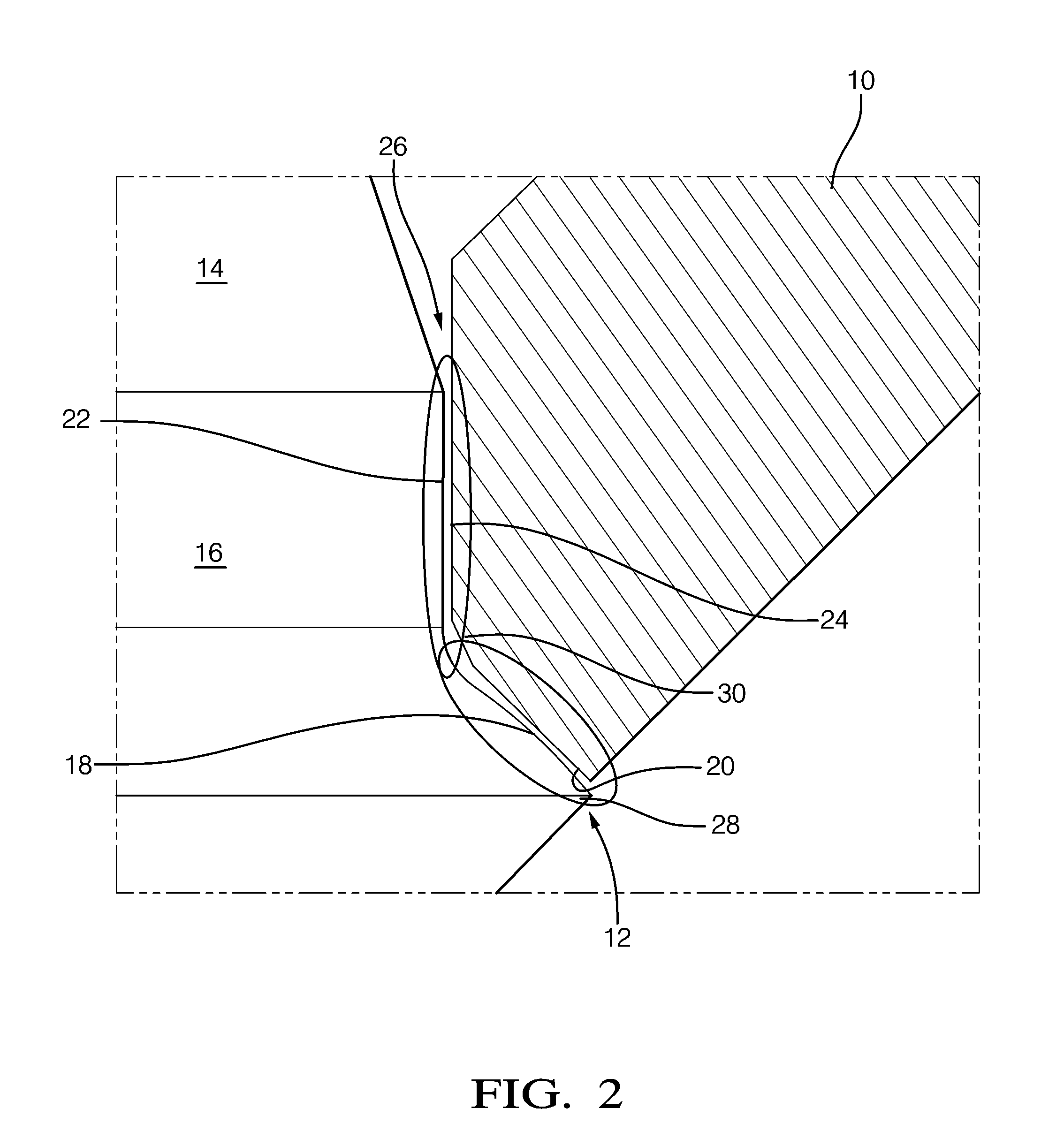
[0019]A fuel injector nozzle has two functions:[0020]1—To deliver the right amount of fuel in the combustion chamber (metering).[0021]2—To generate a spray suitable for the combustion.

[0022]For the known injectors, the dependence of the static flow rate (i.e. flow rate with the injector fully open) on the injector stroke is too high.

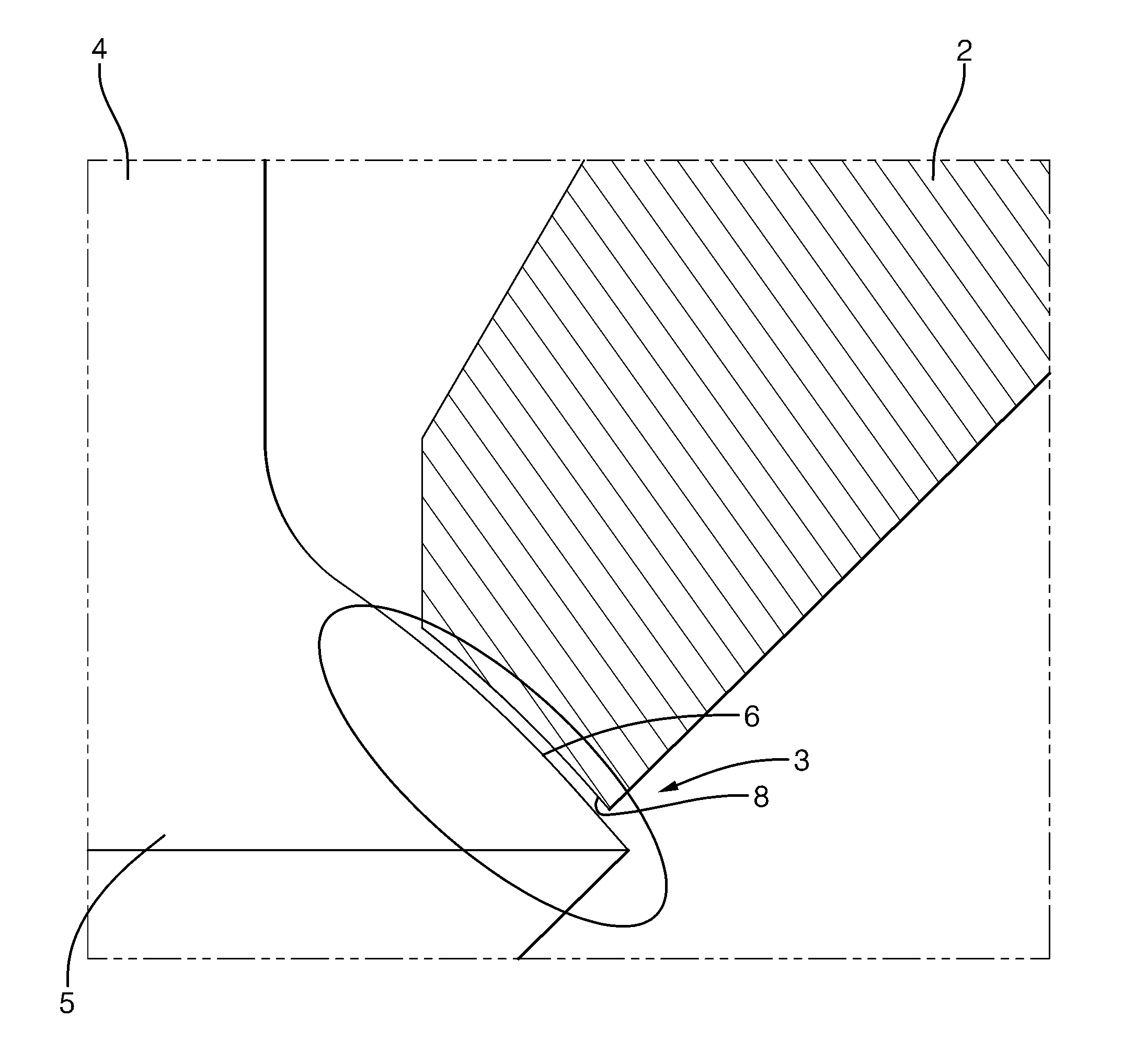
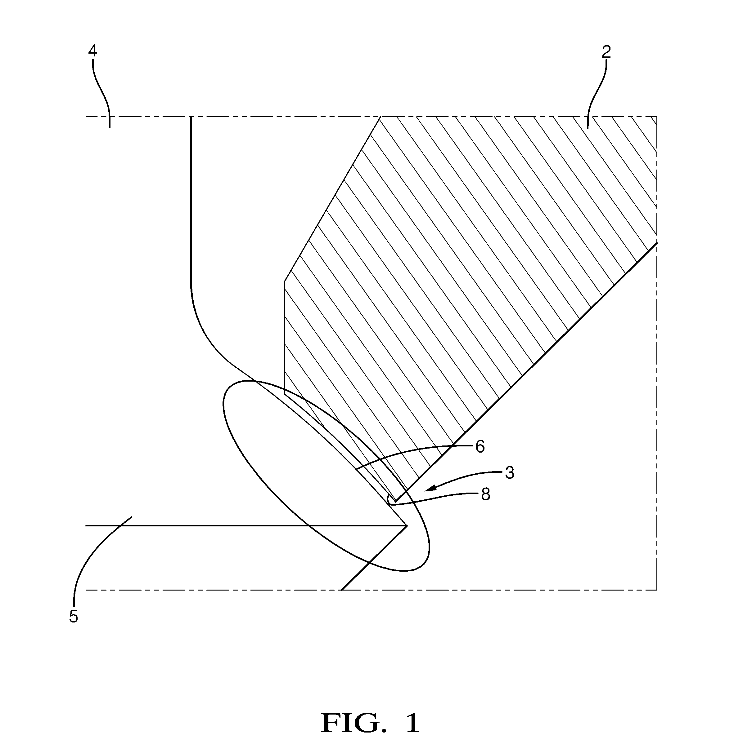
[0023]With the known fuel injectors, the flow rate variation is 1 g / s per μm stroke (3.3% of the nominal value). To ensure reliable operation and to avoid excessive variation in the fuel flow rate caused by variation in the maximum pintle stroke due to manufacturing tolerances and thermal effects and valve wear, the injector specification requires a variation of the flow rate of no more than 2% per μm lift. The current nozzle design (shown in FIG. 1) does not meet such requirement as the metering flow area is directly link to the injector stroke and its variation is 3.4% perμm stroke variation.

[0024]The present invention achieves the objectives of improv...


PUM

PropertyMeasurementUnit
Flow rateaaaaaaaaaa
Viscosityaaaaaaaaaa
Densityaaaaaaaaaa

Abstract

A fuel injector comprising an injector body having a spray aperture; a pintle extending within the injector body for axial movement between a closed position and an open position; said pintle head comprising a tapered portion engageable against the valve seat of the spray aperture and a cylindrical portion upstream of said tapered portion, an annular channel being provided defining a first part of a flow passage upstream of the spray aperture, wherein a discontinuity is provided downstream of the annular channel and upstream of the spray aperture to generate cavitation when the pintle stroke exceeds a predetermined limit to thereby generate a virtual channel of constant cross section downstream of the annular channel whereby the flow rate of the fuel flowing through said spray aperture is substantially independent of the stroke of the pintle when the pintle is in its open position.

Description

TECHNICAL FIELD[0001]The present invention relates to a fuel injector and in particular to a fuel injector for direct injection of gasoline into the combustion chamber of an internal combustion engine.BACKGROUND OF THE INVENTION[0002]A typical outwardly opening fuel injector is shown in FIG. 1, comprising, a valve body having a tip portion 2 defining a spray aperture 3, a pintle 4 or valve stem extending within the tip portion 2 for axial movement between an extended and a retracted position, the pintle 4 having a head 5 having a tapered portion 6 engageable with a valve seat 8 of the spray aperture to close the spray aperture 3 when the pintle 4 is in its retracted position, a return spring (not shown) biasing the pintle 4 towards its retracted position, an actuating means (not shown), such as a solenoid or piezostack, acting upon the pintle 4 to urge the pintle 4 to its extended position when the actuating means is energised.[0003]Particularly in the case of solenoid actuated inje...

Claims


Application Information

Patent Timeline
IPC IPC(8): B05B1/32F02M61/10B21D51/16
CPCF02M61/08Y10T29/49405F02M61/1873F02M61/1866
Inventor CORBINELLI, GIOVANNIHOFFMANN, GUYROBART, DIDIER
Owner DELPHI TECH INC
Why Eureka
Try Eureka