Barrier Improvements

a technology for barriers and stairways, applied in domestic applications, stairs, applications, etc., can solve the problems of uncoiling and affecting the effect of barriers, incurring additional costs and laborious manipulation at each location, and current methods,

Inactive Publication Date: 2010-01-21
NAPIER DONALD STEWART
View PDF3 Cites 23 Cited by
  • Summary
  • Abstract
  • Description
  • Claims
  • Application Information

AI Technical Summary

Benefits of technology

[0031]An advantage of this is that from a visual point of view, there now can be provided very clean lines indeed with literally nothing showing to a casual observer at least as far as the upper interconnecting system is concerned and it is also readily economic to put into practice because it is a much easier proposition to simply swage a single end of a wire and have a keyhole shape cut by appropriate means, e.g. laser cutting along a lowermost edge into a hollow shape.
[0032]A further advantage is that this arrangement can be adapted for use as a staircase railing, without the need to change the keyhole position or use wires of differing lengths.

Problems solved by technology

It has been known to use multi strand wire especially between respective anchor points but there are difficulties with the current methods and resulting product.
The resulting product is therefore effective in an engineering sense but it has a number of problems both from an aesthetic, practical and economic sense.
The first of the problems is that looping off each wire is a time consuming task and together with this, the attachment at each of spaced apart positions of some anchor bracket such as a U shaped bracket or a D link of some sort incurs further costs and a laborious manipulation at each location.
Further, multi strand and even single strand wire once cut has an end or ends which can be ragged, or even if not ragged, can uncoil and effect quite a sharp cut if a person rubs against them.
Furthermore, it is difficult to swage each wire to the same length.
There is further difficulty where animals might be involved where these might rub against the ends and could quite easily harm themselves.
A separate tensioning system could in another instance include for each wire length, a turnbuckle, but this requires finishing off of ends of wires, and as well does not provide a good visual impact as well incurs costs of extra fittings.

Method used


Image

  • Barrier Improvements
  • Barrier Improvements
  • Barrier Improvements

Examples


first embodiment

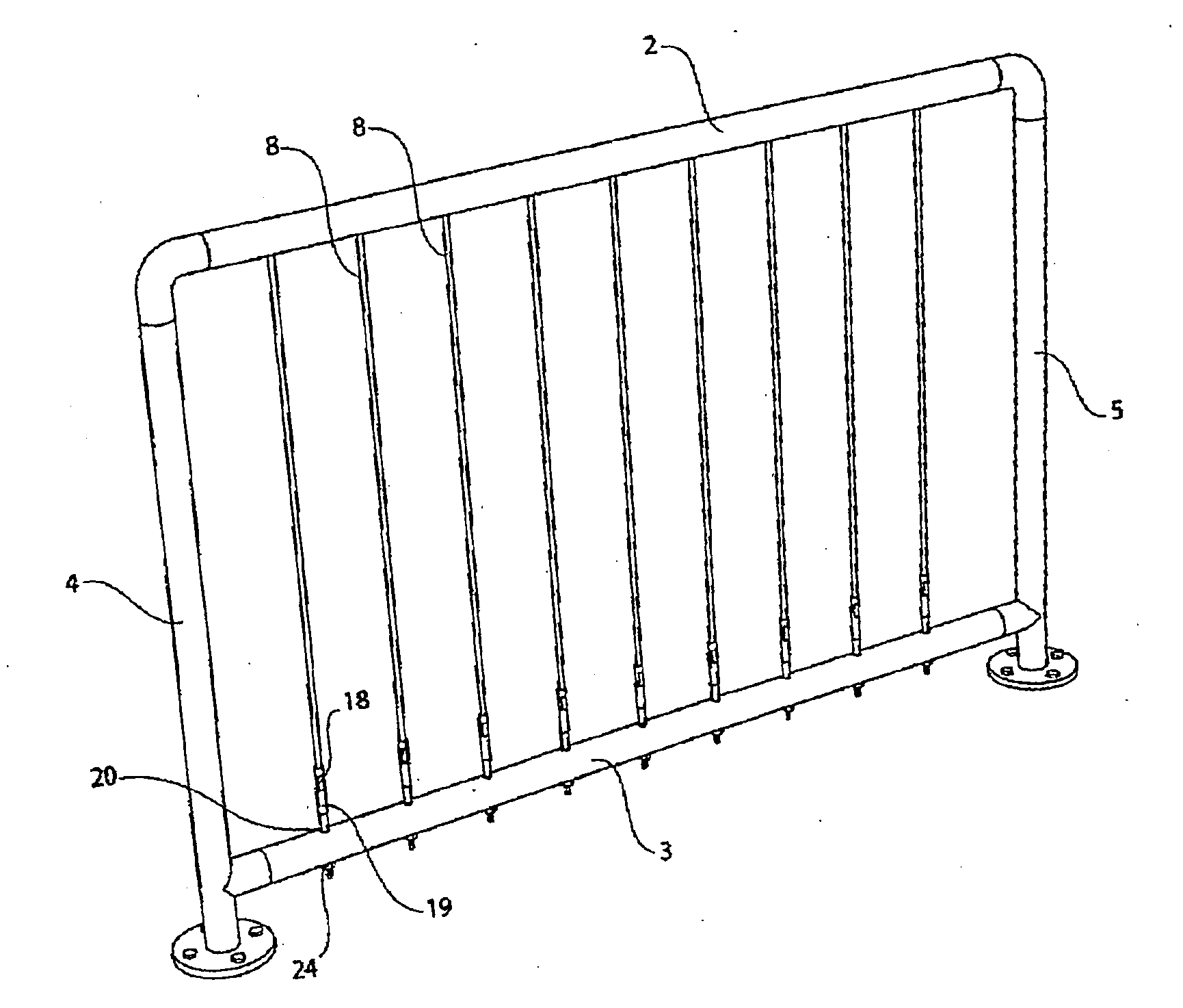
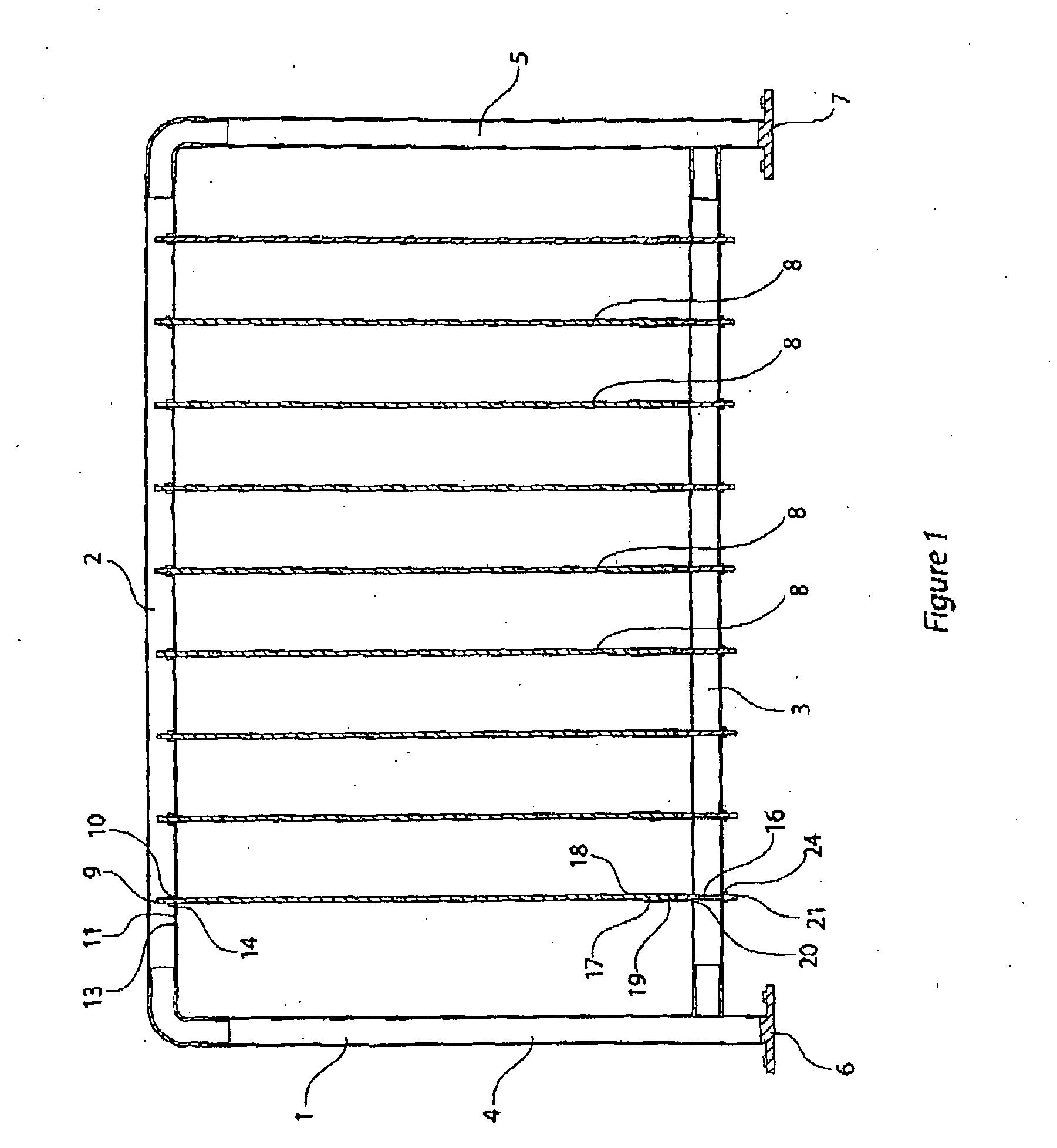
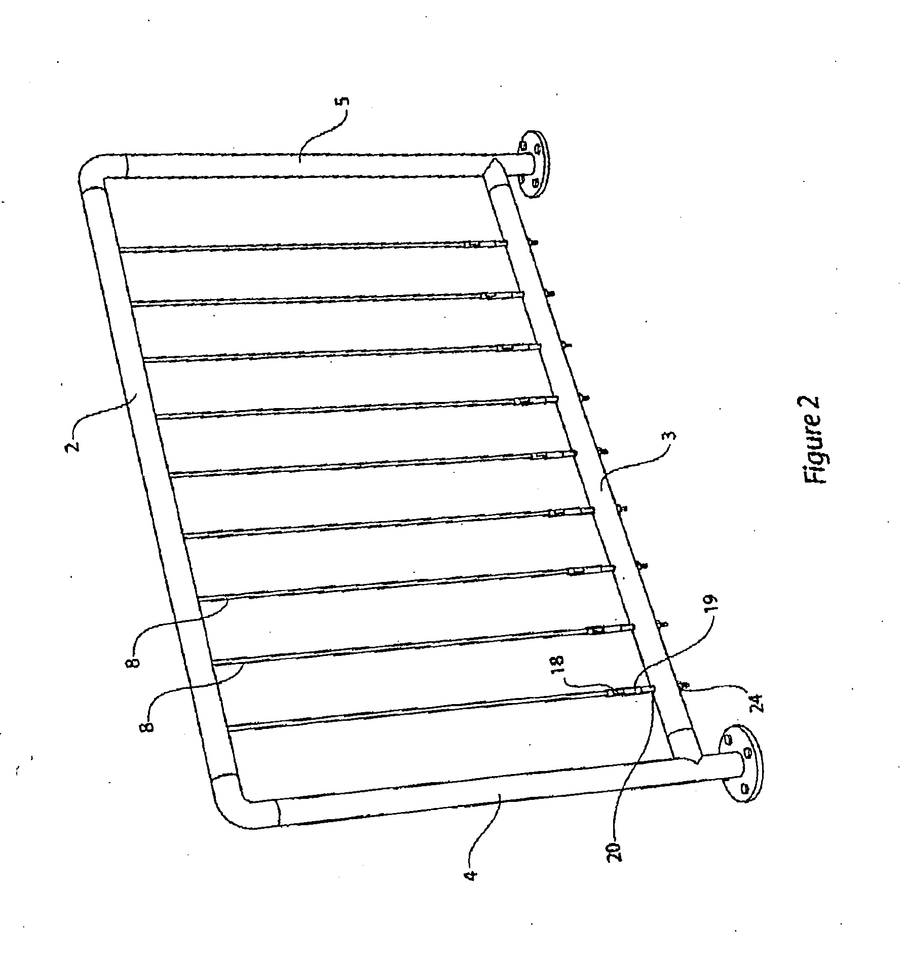
[0048]Referring in detail the embodiments and in particular to the first embodiment as shown in FIGS. 1 and 2, there is firstly shown a surrounding frame 1 which includes and provides an upper railing 2 and a lower railing 3 which is parallel to the first said railing 2.

[0049]These references to upper and lower are relative.

[0050]There are two vertical posts 4 on one side and 5 on the other which are anchored to the ground as at 6 in one case and 7 in the other.

[0051]There are a plurality of wires 8 each of which is spaced one from the other and in each case they are both parallel with respect to the other and spaced at equal distance apart from one another.

[0052]In order to provide an adequate barrier effect however, they are each to be tightened or tensioned and in the first instance and in accord with this embodiment, each uppermost end as shown at 9 has a ferrule swaged around an end or close to the end so as to be tightly anchored thereto.

[0053]The technique of swaging in this ...

second embodiment

[0059]Now referring to the second embodiment, this now simply shows a surrounding frame 30 of hollow tube which is formed in appropriate manner and such a frame then can be used to provide a barrier for any appropriate application for instance as a gate, or as an independent module for appropriate location between vertical posts as is shown in this case where the posts are shown at 31, 32.

[0060]In this case again then each of the wires 33 are multi strand stainless steel and have an upper end swaged and there is a keyhole slot such as at 35 which has a larger end 36 through which the swaged end 34 will pass, and by having the alignment of the respective tensioning system shown at 37 such that the larger portion of the keyhole 36 is slightly offset so that the narrower portion of the keyhole slot is actually closer to the tension assembly 37, then by applying tension, the position of the bulbous end 34 will be tending to be kept in the narrower end and therefore in the interlocking p...


PUM

PropertyMeasurementUnit
key hole shapeaaaaaaaaaa
sizeaaaaaaaaaa
tensionaaaaaaaaaa

Abstract

A barrier provided by a plurality of wires, spaced apart one from the other and crossing between spaced apart elongate members, at least one of the wires having a bulbous end, and a first of the elongate members having an aperture either in or attached thereto, through which, in one position, the bulbous end of the wire is adapted to pass through, and in a second barrier providing position, is intercepted against withdrawal there from.

Description

FIELD OF THE INVENTION[0001]This invention relates to barrier improvements including a barrier, an assembly including a barrier, and a method of constructing a barrier.[0002]It is currently known to use a plurality of wires held under tension between end members and where the wires are spaced apart and are parallel one with respect to the other.[0003]The term “wire” is intended, unless the context restricts such broader interpretation, both single strand and multi strand wires and will also include coated and uncoated wires where for instance a coated wire may include an outer surrounding plastics material.[0004]It has been known to use multi strand wire especially between respective anchor points but there are difficulties with the current methods and resulting product.[0005]We are in this case directing the discussion to a wire tightening system which may include a threaded shaft to which at one end there is swaged a wire, and at the other end of wire there is a ferrule.[0006]The ...

Claims


Application Information

Patent Timeline
Patent Type & Authority Applications(United States)
IPC IPC(8): E04H17/02E04H17/14B23P11/00
CPCY10T29/49826E01F13/022E04F11/1859E04F2011/1821E04F2011/1823
Inventor NAPIER, DONALD STEWART
Owner NAPIER DONALD STEWART
Why Eureka
Try Eureka