Power efficient charge pump with controlled peak currents

a charge pump and peak current technology, applied in the field of charge pumps, can solve the problem of excessive in-rush currents

Inactive Publication Date: 2010-01-21
ANALOG DEVICES INC
View PDF12 Cites 77 Cited by
  • Summary
  • Abstract
  • Description
  • Claims
  • Application Information

AI Technical Summary

Problems solved by technology

One problem of the charge pump in FIG. 1 is that it has no in-rush current protection and its in-rush current may become exceedingly large.

Method used


Image

  • Power efficient charge pump with controlled peak currents
  • Power efficient charge pump with controlled peak currents
  • Power efficient charge pump with controlled peak currents

Examples


Embodiment Construction

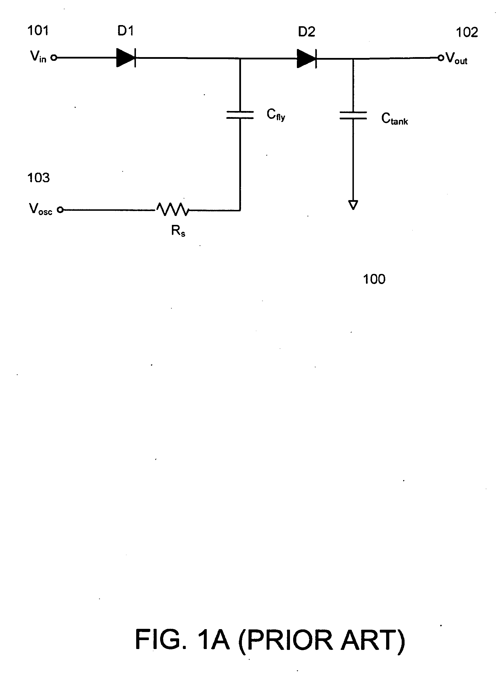
[0015]A charge pump of the present invention may overcome the disadvantages noted above by using its peak current limit resistor to limit its in-rush current. The peak current limit resistor may be removed from the discharging current path of the flying capacitor and put between the input voltage source and the flying capacitor. An additional advantage of such a charge pump is that, when being coupled to a boost converter or other switching regulator utilizing an inductor, it may avoid unnecessary power dissipation caused by the peak current limit resistor when the flying capacitor receives energy from the inductor.

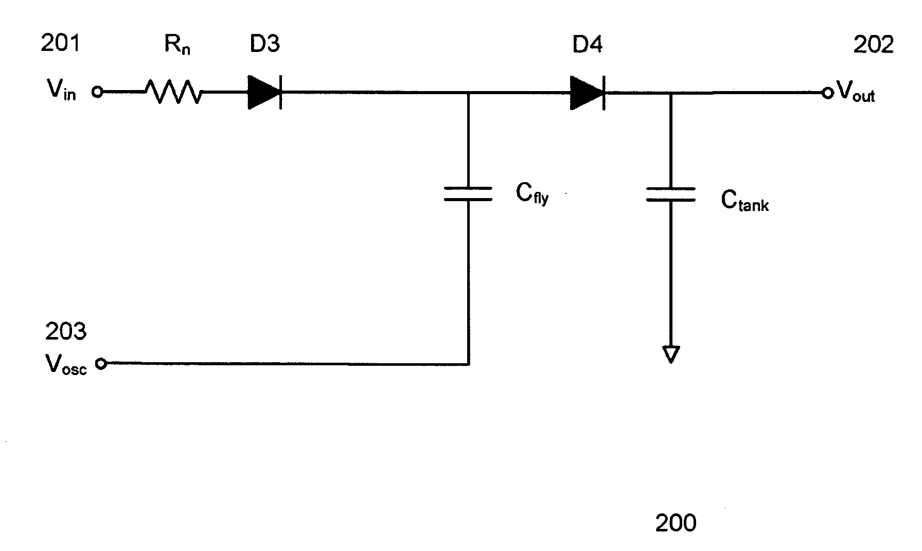
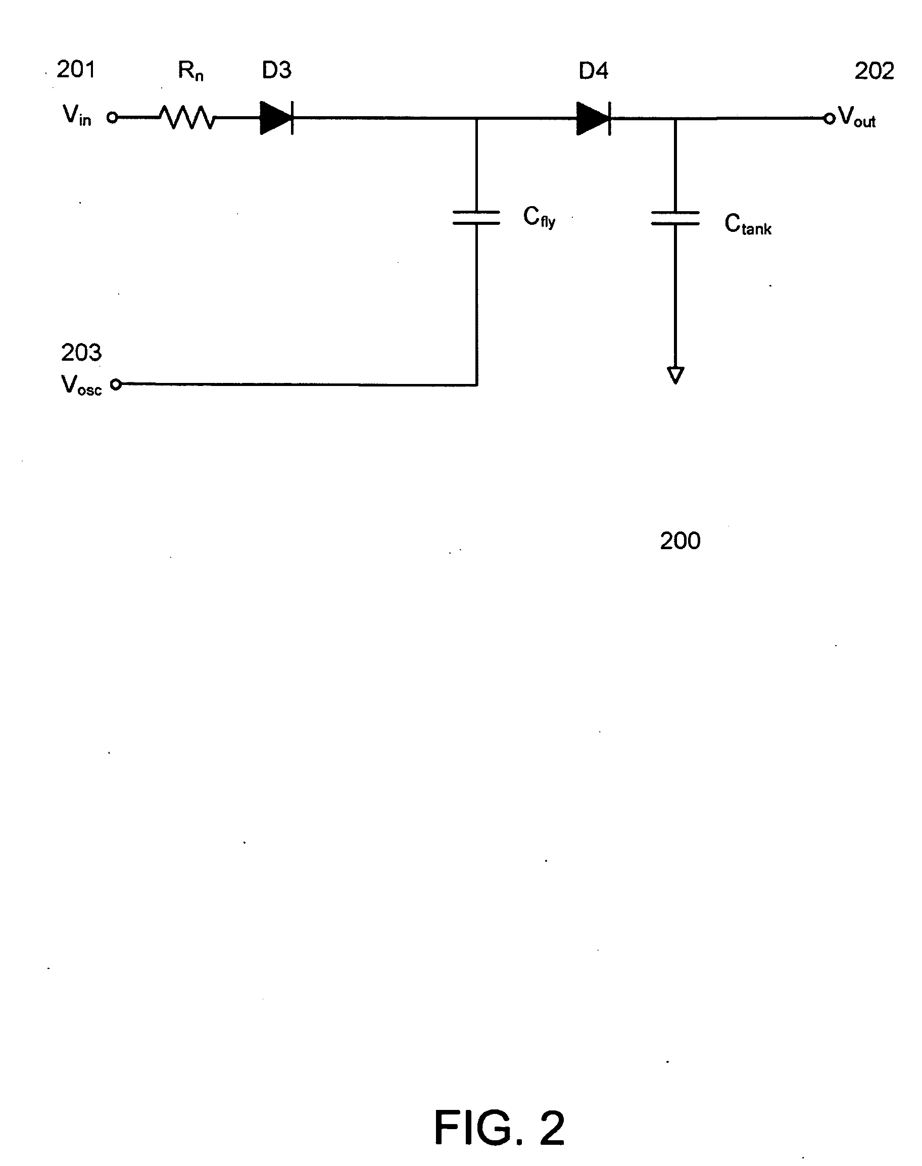
[0016]FIG. 2 is a circuit schematic depicting a charge pump according to one embodiment of the present invention. As shown, an input node 201 of a charge pump 200 may be coupled to an input voltage source Vin. The charge pump 200 may provide an output voltage Vout at its output node 202. A current limit resistor Rn and diodes D3 and D4 may be coupled in series between the...


PUM


Abstract

A charge pump which uses a current limit resistor to limit in-rush current and peak currents. An additional advantage of such a charge pump is that, when being coupled to a boost converter or other switching converter utilizing an inductive energy storage element, it may avoid unnecessary power dissipation caused by the current limit resistor.

Description

BACKGROUND INFORMATION[0001]The present invention relates generally to charge pumps.[0002]Charge pumps may produce a high voltage from a lower voltage source, and are often used in portable electronic devices, such as laptop computers, mobile phones, navigation devices, and media players. FIG. 1 illustrates a currently available charge pump. As shown, an input node 101 of a charge pump 100 may be coupled to an input voltage source Vin. The charge pump 100 may provide an output voltage Vout at its output node 102. Diodes D1 and D2 may be coupled in series between the input node 101 and the output node 102. A tank capacitor Ctank may be coupled between the output node 102 and ground. The top of a flying capacitor Cfly may be coupled to the junction of the diodes D1 and D2, and the bottom of Cfly may be coupled to an oscillating voltage Vosc, provided at a node 103, via a peak current limit resistor Rs.[0003]Consider one example in which, Vin=10 v, Rs=10Ω, Cfly=100 nf, Ctank=1 uf, and ...

Claims


Application Information

Patent Timeline
Patent Type & Authority Applications(United States)
IPC IPC(8): G05F3/00
CPCH02M3/07H02M1/36
Inventor BARROW, JEFFREY G.
Owner ANALOG DEVICES INC
Why Eureka
Try Eureka