Nuclear reactor components including material layers to reduce enhanced corrosion on zirconium alloys used in fuel assemblies and methods thereof

Inactive Publication Date: 2010-01-21
GLOBAL NUCLEAR FUEL -- AMERICAS
View PDF3 Cites 20 Cited by
  • Summary
  • Abstract
  • Description
  • Claims
  • Application Information

AI Technical Summary

Benefits of technology

[0007]Example embodiments are directed to providing a thin, adherent coating on the surfaces of nuclear reactor components that are known to cause increased corrosion on adjacent zirconium alloy structures and methods of reducing the increased corrosion. Example e

Problems solved by technology

The corrosion, also known as “shadow” corrosion, weakens the Zi

Method used


Image

  • Nuclear reactor components including material layers to reduce enhanced corrosion on zirconium alloys used in fuel assemblies and methods thereof
  • Nuclear reactor components including material layers to reduce enhanced corrosion on zirconium alloys used in fuel assemblies and methods thereof
  • Nuclear reactor components including material layers to reduce enhanced corrosion on zirconium alloys used in fuel assemblies and methods thereof

Examples


Embodiment Construction

[0018]Various example embodiments will now be described more fully with reference to the accompanying drawings in which some example embodiments are illustrated. In the drawings, the thicknesses of layers and regions may be exaggerated for clarity.

[0019]Detailed illustrative embodiments are disclosed herein. However, specific structural and functional details disclosed herein are merely representative for purposes of describing example embodiments. This invention may, however, be embodied in many alternate forms and should not be construed as limited to only example embodiments set forth herein.

[0020]Accordingly, while example embodiments are capable of various modifications and alternative forms, embodiments thereof are shown by way of example in the drawings and will herein be described in detail. It should be understood, however, that there is no intent to limit example embodiments to the particular forms disclosed, but on the contrary, example embodiments are to cover all modifi...


PUM


Abstract

Example embodiments are directed to providing a thin, adherent coating on the surfaces of nuclear reactor components, which are known to cause increased corrosion on adjacent zirconium alloy structures, and methods of reducing the increased corrosion. Example embodiments include coatings being structurally bonded to components such that the difference in the corrosion potential between a coated component and a zirconium alloy component is less than that between a component without the coating and the zirconium alloy component.

Description

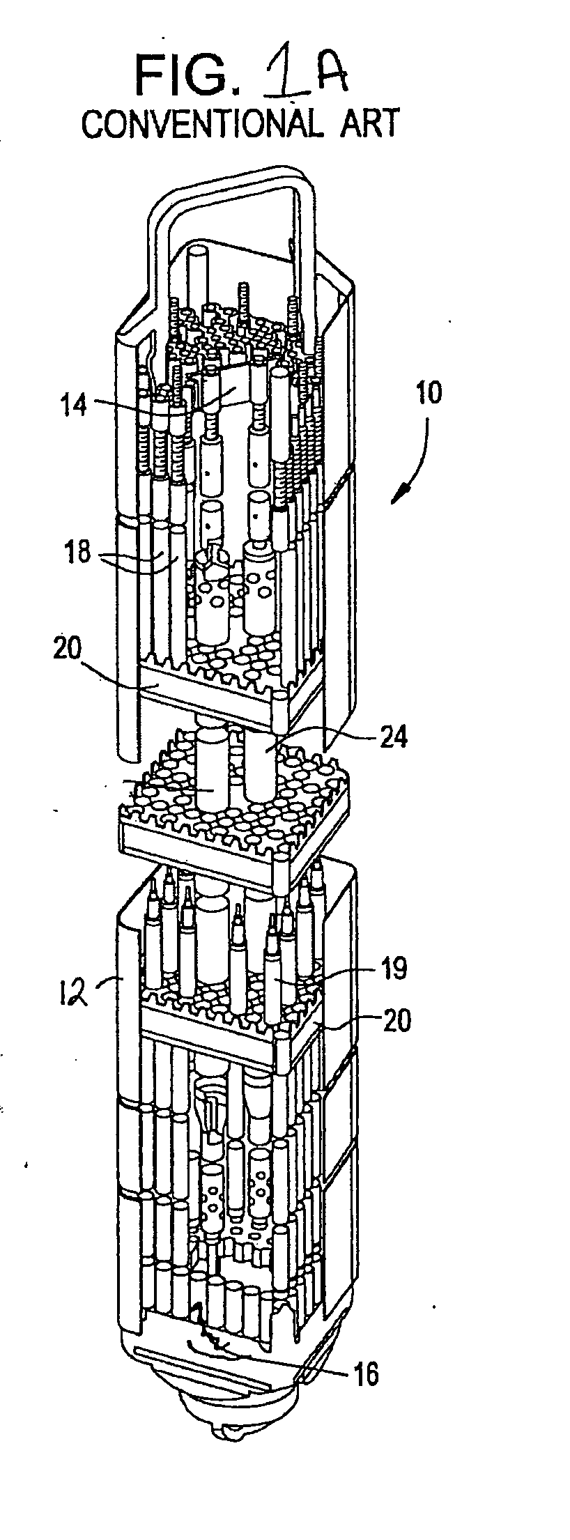
BACKGROUND[0001]1. Field[0002]Example embodiments generally relate to nuclear reactors including components that have reduced shadow corrosion on zirconium alloys and methods thereof.[0003]2. Description of Related Art[0004]Generally, nuclear power plants include a reactor core having fuel arranged therein to produce power by nuclear fission. A common design in nuclear power plants is to arrange fuel in a plurality of fuel rods bound together as a fuel assembly, or fuel bundle, placed within the reactor core. These fuel rods typically include several elements joining the fuel rods to assembly components at various axial locations throughout the assembly.[0005]As shown in FIG. 1, a conventional fuel bundle 10 of a nuclear reactor, such as a BWR, may include an outer channel 12 surrounding an upper tie plate 14 and a lower tie plate 16. A plurality of full-length fuel rods 18 and / or partial length fuel rods 19 may be arranged in a matrix within the fuel bundle 10 and pass through a pl...

Claims


Application Information

Patent Timeline
IPC IPC(8): G21C9/00G21F1/08
CPCG21C17/0225G21C21/02G21C3/356Y02E30/30
Inventor LUTZ, DANIEL R.KIM, YOUNG JINLIN, YANG-PI
Owner GLOBAL NUCLEAR FUEL -- AMERICAS
Why Eureka
Try Eureka