
Systems and methods for remote display of an enhanced image

a technology of enhanced images and remote display, applied in the field of vision systems, can solve problems such as visual hindrances, insufficient vertical visualization above and below the aircraft, and drawbacks of imagery systems

Inactive Publication Date: 2010-01-21
THE BOEING CO
View PDF54 Cites 41 Cited by
  • Summary
  • Abstract
  • Description
  • Claims
  • Application Information

AI Technical Summary

Benefits of technology

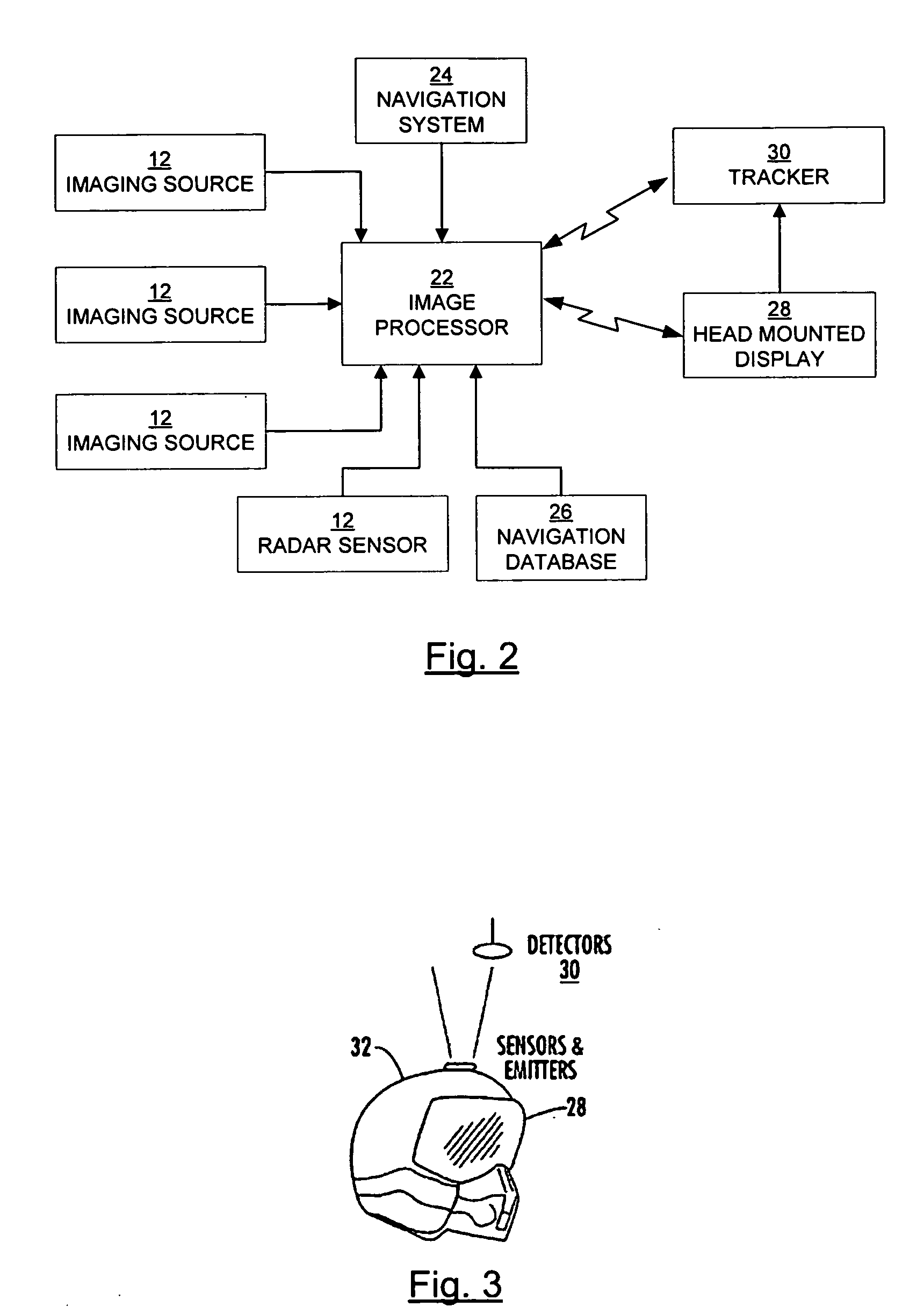
[0017]A system and method are therefore provided in which an enhanced vision system creates enhanced images and transmits the enhanced images via a wireless link for display to a remote user, thereby enabling remote viewing of multiple lines of sight. Additionally, one or more transmission characteristics may be modified according to the available communication bandwidth.

Problems solved by technology

However, there are instances where these various instruments become the pilot's only resource for information because the pilot's vision is hindered.
Further, some visual hindrances are due to the field of view limitations of the aircraft itself.
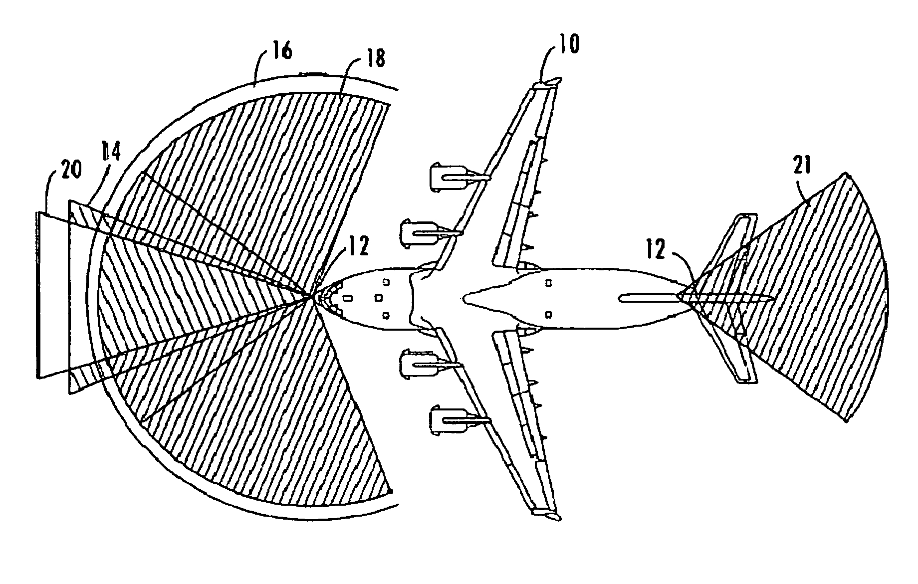
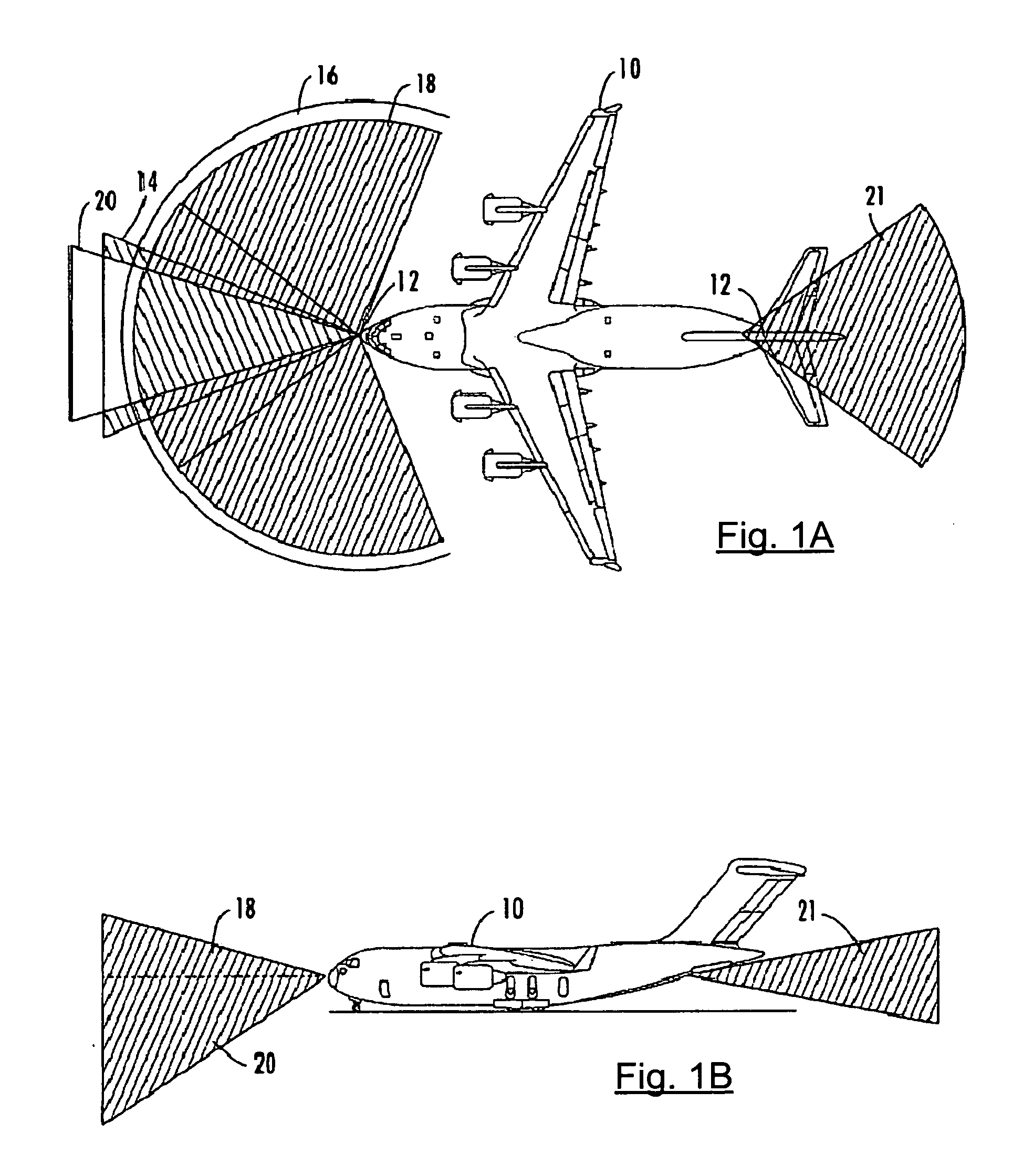
Many aircraft cockpits have a field of view that is typically limited to a forward facing area that does not provide the pilot with adequate visualization to the sides and rear of the aircraft and also does not provide adequate vertical visualization above and below the aircraft.
This type of imagery system has drawbacks, however.
The gimbal imposes drag and increases the radar signature of the UAV.
Furthermore, when the camera is directed to view to the side or below the aircraft, as may be done for targeting purposes, there is no vision along the flight path of the UAV.
This may be particularly problematic when the pilot requires a view along the flight path while a separate weapons operator requires a view below the UAV to target a weapon.
Because imagery from the UAV is transmitted to the GCS via the wireless link, issues may arise because of bandwidth limitations.
However, even when it is not possible to transmit full bandwidth imagery to the GCS, that imagery is available on board the vehicle and may be processed to provide warnings or other cueing to the remote human operators.

Method used


Image

  • Systems and methods for remote display of an enhanced image
  • Systems and methods for remote display of an enhanced image
  • Systems and methods for remote display of an enhanced image

Examples


Embodiment Construction

[0029]The present invention now will be described more fully hereinafter with reference to the accompanying drawings, in which some, but not all embodiments of the inventions are shown. Indeed, these inventions may be embodied in many different forms and should not be construed as limited to the embodiments set forth herein; rather, these embodiments are provided so that this disclosure will satisfy applicable legal requirements. Like numbers refer to like elements throughout.

[0030]Embodiments of the present invention provide systems and methods for use in enhanced vision displays. The systems and methods of embodiments of the present invention receive image data from a plurality of sources located at different positions on a vehicle or in an area of interest. The systems and methods assimilate the images from each source into a composite image. The system may also be provided with synthetic data from a data source. Both sensors and synthetic data sources are referred to herein as a...


PUM


Abstract

A system for providing remote display of an enhanced image comprises at least one image source and a processing element. The processing element is capable of receiving data from the image source, creating an enhanced image with the received data, and transmitting the enhanced image via a wireless link to a display device capable of displaying the enhanced image. The processing element may create the enhanced image by stitching image data from at least two image sources having different fields of view, fusing image data from at least two image sources having different image modalities, or combining image data from at least one image source with synthetic image data. The processing element may be further capable of modifying at least one transmission characteristic based on a bandwidth of the wireless link. The transmission characteristic may be selected from the group comprising field of view, frame rate, resolution, and compression.

Description

FIELD OF THE INVENTION[0001]The present invention relates generally to vision systems, and more particularly, to vision systems capable of transmitting enhanced images to remote display devices.BACKGROUND OF THE INVENTION[0002]Despite the advent of many flight navigational aids, one of the most important tools for navigation of aircraft remains visual navigation. Many of today's aircrafts include various safety features such as on board radar, ground proximity warning systems, etc. that provide a pilot with added information about the airspace surrounding the aircraft. These systems are a tremendous resource to aid the pilot in obtaining better situational awareness during flight, by allowing the pilot to further interpret what the pilot is visually observing. However, there are instances where these various instruments become the pilot's only resource for information because the pilot's vision is hindered.[0003]Visual hindrances may be due to bad weather, such as fog, snow, or rain...

Claims


Application Information

Patent Timeline
Patent Type & Authority Applications(United States)
IPC IPC(8): G06F17/00G09G5/00
CPCB64D47/08G06F3/14G09G2340/02G09G2380/12G09G2350/00G09G2370/16G09G2340/12B64U20/87
Inventor SANDERS-REED, JOHN N.
Owner THE BOEING CO
Features
  • Generate Ideas
  • Intellectual Property
  • Life Sciences
  • Materials
  • Tech Scout
  • Unparalleled Data Quality
  • Higher Quality Content
  • 60% Fewer Hallucinations
Learn More