Surface texture measuring instrument and measuring method

Active Publication Date: 2010-01-28
MITUTOYO CORP
View PDF7 Cites 13 Cited by
  • Summary
  • Abstract
  • Description
  • Claims
  • Application Information

AI Technical Summary

Benefits of technology

[0009]An object of the invention is to provide a surface texture measuring instrument and a measuring method capable of co

Problems solved by technology

However, in order for the surface texture measuring instrument disclosed in Document 1 to totally automatically conduct the positioning of the workpiece, the surface texture measuring instrument is required to use a combination of a table inclination device for inclining the table and an electric column device for moving the detector in Z-axis direction, which tends to result in a large-scale system configuration of the surface texture measuring instrument.
Accordingly, a wider installation space may be required

Method used


Image

  • Surface texture measuring instrument and measuring method
  • Surface texture measuring instrument and measuring method
  • Surface texture measuring instrument and measuring method

Examples


first exemplary embodiment

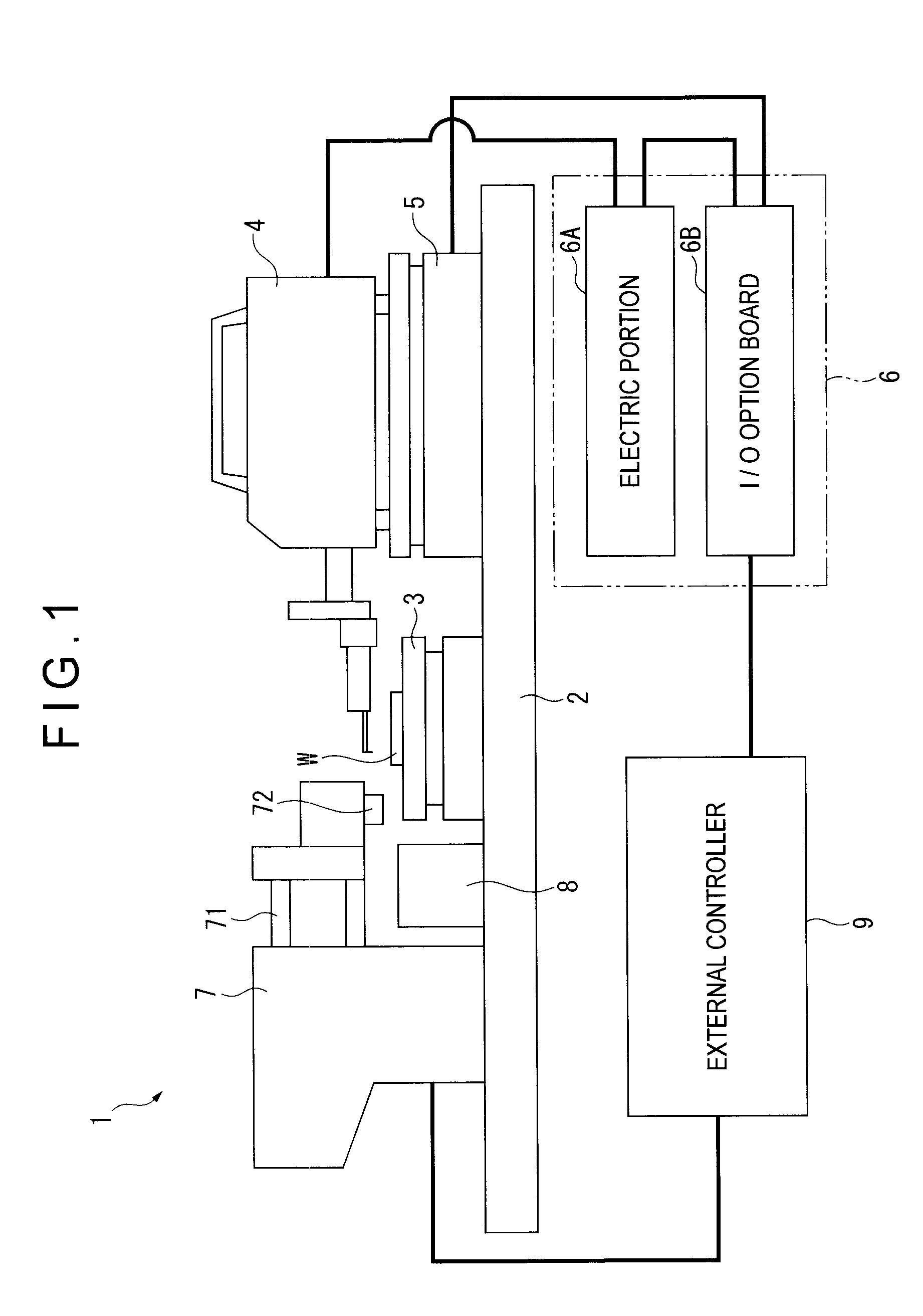
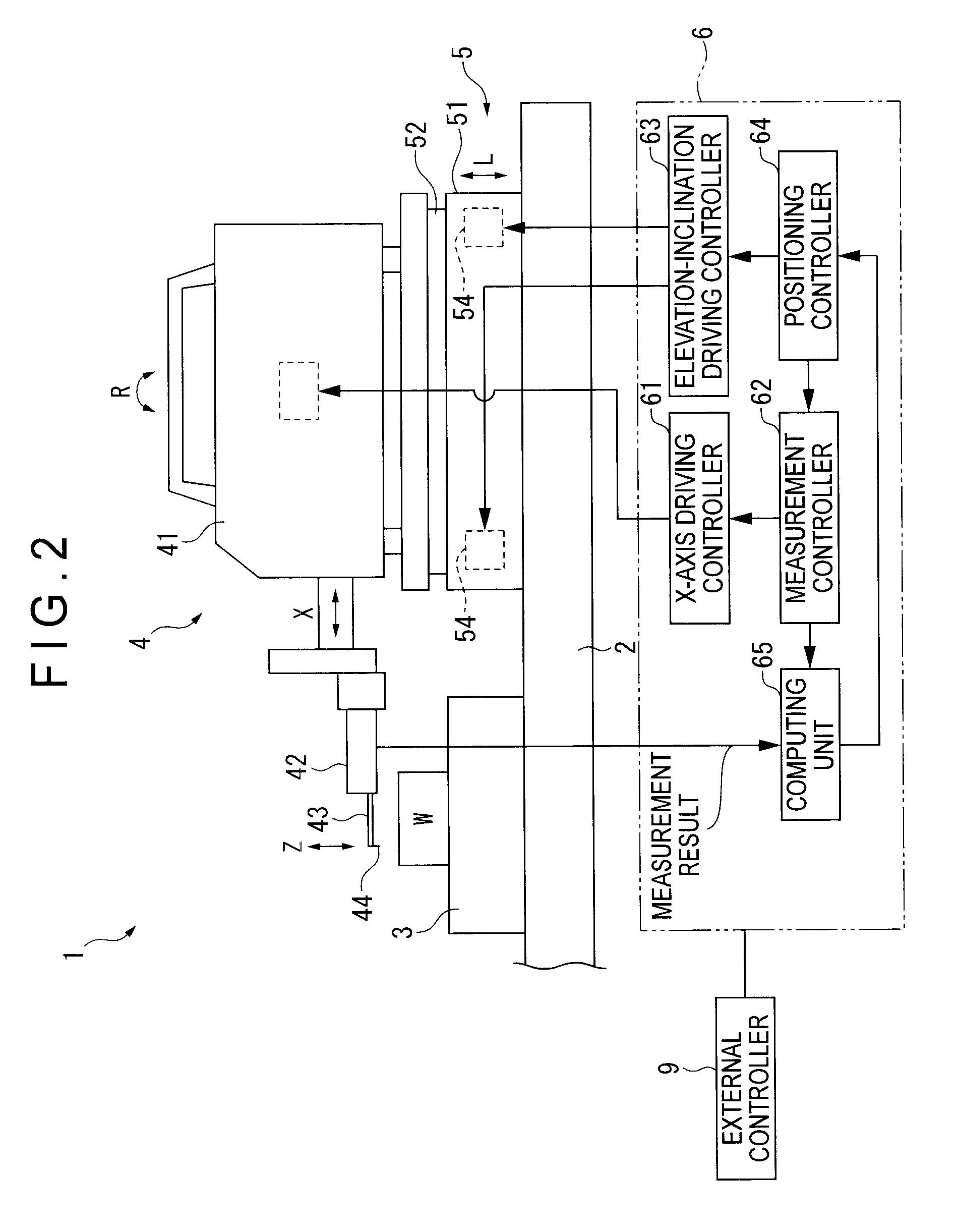
[0028]FIG. 1 shows the entire structure of a surface texture measuring instrument 1 according to the first exemplary embodiment. FIG. 2 is a block diagram for explaining a structure of a controller for the surface texture measuring instrument 1.

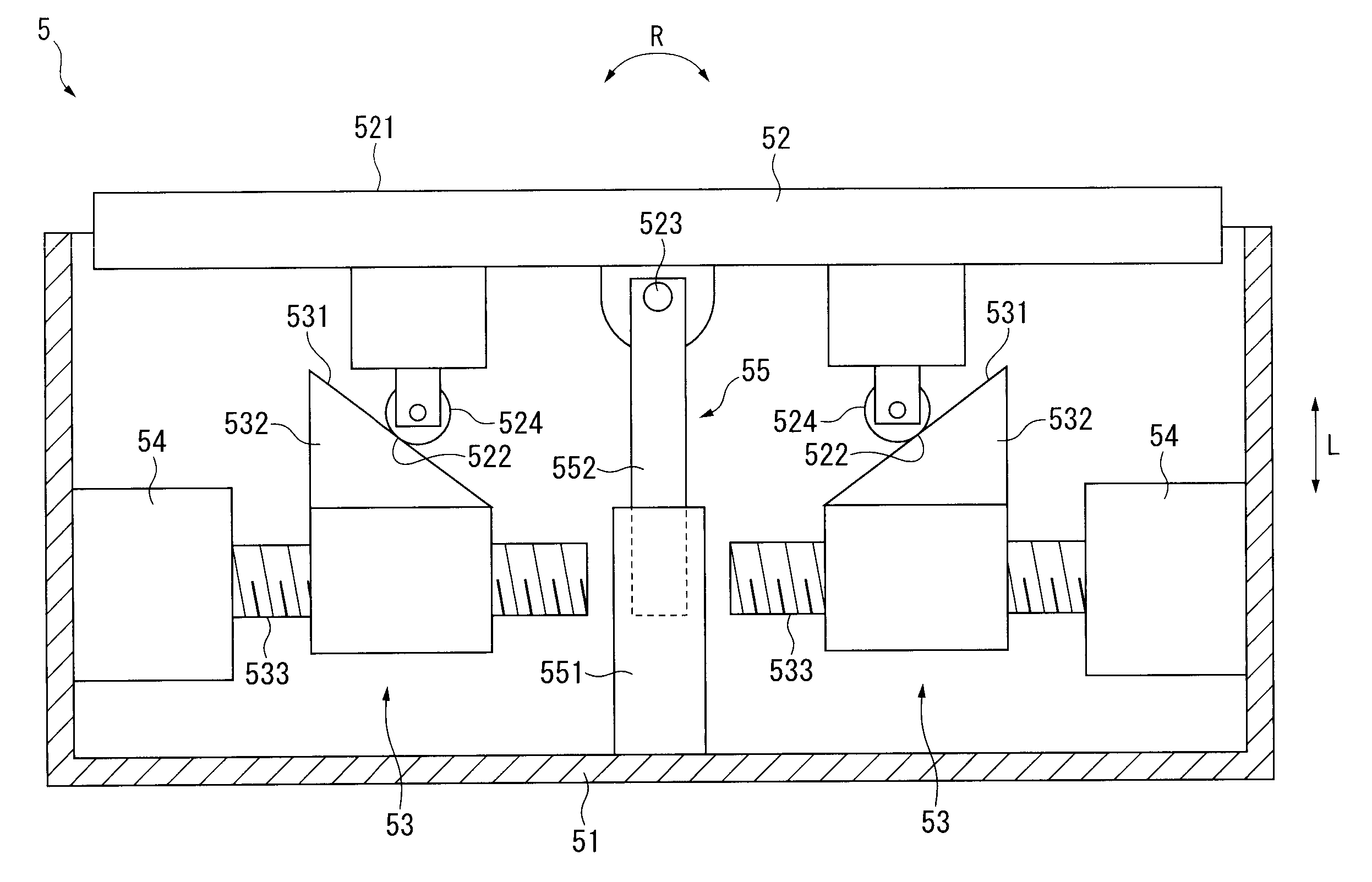
[0029]In FIG. 1, the surface texture measuring instrument 1, which is for conducting form measurements on a workpiece W such as roughness measurements and contour measurements, includes: a platform 2; a stage 3 on which the workpiece W is placed; a measuring device 4; an elevation inclination adjuster 5 (auto-setting / auto-leveling table) on which the measuring device 4 is placed; and a controller 6 for automatically conducting a positioning of the measuring device 4 relative to the workpiece W. The measuring device 4 is movable by the elevation inclination adjuster 5.

[0030]In addition to the stage 3 and the elevation inclination adjuster 5, a workpiece feeder 7 (external device worked in conjunction with the measuring device 4) and a parts bo...

second exemplary embodiment

[0070]Next, an elevation inclination adjuster 5A according to a second exemplary embodiment of the invention will be described with reference to FIG. 7.

[0071]FIG. 7 is a lateral view schematically showing a driving mechanism for the elevation inclination adjuster 5A. The elevation inclination adjuster 5A is different from the above elevation inclination adjuster 5 according to the first exemplary embodiment in configurations of moving units 53A and fulcrum 55A. The other structures are substantially the same.

[0072]Specifically, the moving units 53A each include: a slider 532A having a horizontal opposed surface 534 opposed to the table 52; and a lead screw 533A (slider moving member) connected to the driving source 54 for moving the slider 532A in the L-axis direction.

[0073]More specifically, the driving source 54 and the lead screw 533A are supported on the base 51 such that their rotation axes vertically extend. The rotation driving force of the driving source 54 is transmitted to...

third exemplary embodiment

[0086]Next, an elevation inclination adjuster 5B according to a third exemplary embodiment of the invention will be described with reference to FIG. 10.

[0087]FIG. 10 is a lateral view schematically showing a driving mechanism for the elevation inclination adjuster 5B. The elevation inclination adjuster 5B is different from the elevation inclination adjusters of the above exemplary embodiments in that the fulcrum 523B coincides with either one of the points of action at two positions. The other structures are substantially the same.

[0088]Either one of the pair of moving units 56, 57 supports the point of action 522, and also serves as a point-of-action moving unit 56 for moving the point of action 522 in a direction in which the distance between the point of action 522 and the base 51 is increased or decreased (i.e., distance increasing / decreasing direction).

[0089]On the other hand, the other one of the pair of moving units 56, 57 supports the fulcrum 523B, and also serves as a fulcr...


PUM


Abstract

A surface texture measuring instrument includes: a measuring device that includes a detector for detecting surface texture of a workpiece and an X-axis movement mechanism for moving the detector in a measurement direction; an elevation inclination adjuster capable of adjusting an elevation position and an inclination angle of a table on which the measuring device is mounted; a stage on which the workpiece is mounted; and a controller that controls the measuring device and the elevation inclination adjuster. The controller includes: a measurement controller that controls the X-axis movement mechanism to conduct a preliminary measurement and main measurement of the workpiece; a computing unit that acquires a result of the preliminary measurement from the detector and obtains an inclination angle of the workpiece at which the workpiece is inclined to the measurement direction; and a positioning controller for adjusting the inclination angle of the table based on the obtained inclination angle.

Description

[0001]The entire disclosure of Japanese Patent Application No. 2008-193884, filed Jul. 28 2008, is expressly incorporated by reference herein.BACKGROUND OF THE INVENTION[0002]1. Field of the Invention[0003]The present invention relates to a surface texture measuring instrument for conducting form measurements such as roughness measurements and contour measurements, and a method of the measurement.[0004]2. Description of Related Art[0005]To date, surface texture measuring instruments for conducting roughness measurements on workpieces having, for instance, cylindrical and conical edge lines are known (see, for instance, document 1: JP-A-8-29153).[0006]The surface texture measuring instrument disclosed in Document 1, which includes a driving mechanism for moving the workpiece relatively with respect to a detector, conducts a provisional measurement before conducting a main measurement and totally automatically corrects a posture of the workpiece mounted on a table to the standard post...

Claims


Application Information

Patent Timeline
IPC IPC(8): G01B21/30G01N19/00G01B5/00
CPCG01B5/0004G01B5/28G01B5/20
Inventor KANEMATSU, TOSHIHIROMISHIMA, HIDEKIHAMA, NOBUYUKI
Owner MITUTOYO CORP
Why Eureka
Try Eureka