Composite Hub for High Energy-Density Flywheel

a composite hub and high energy density technology, applied in mechanical energy handling, vibration suppression adjustments, mechanical equipment, etc., can solve the problems of limited performance of carbon fiber composite rims, unable to reach their maximum capability at a significantly higher operating speed, etc., to achieve maximum energy density and maximize the performance of composite hubs

Inactive Publication Date: 2010-01-28
BEACON POWER LLC
View PDF0 Cites 58 Cited by
  • Summary
  • Abstract
  • Description
  • Claims
  • Application Information

AI Technical Summary

Benefits of technology

[0018]It is an object of the present invention to illustrate a flywheel energy storage system comprising a novel rotor system comprising a composite hub, composite rotor and metal shaft, utilized in combination with a switched reluctance motor system, which afford the system the capability of achieving its maximum energy density.
[0019]It is an object of the instant invention to illustrate a flywheel energy storag

Problems solved by technology

Composite hubs have been proposed which are manufactured using a filament-wound process (see reference published paper), but their performance is limited due to the material design limitations imposed by that

Method used


Image

  • Composite Hub for High Energy-Density Flywheel
  • Composite Hub for High Energy-Density Flywheel
  • Composite Hub for High Energy-Density Flywheel

Examples


Embodiment Construction

[0036]The detailed description set forth below in connection with the appended drawings is intended as a description of presently-preferred embodiments of the invention and does not represent the only forms in which the present invention may be constructed and / or utilized. The description sets forth the functions and the sequence of steps for constructing and operating the invention in connection with the illustrated embodiments. However, it is to be understood that the same or equivalent functions and sequences may be accomplished by different embodiments that are also intended to be encompassed within the spirit and scope of the invention, such as flywheel systems with magnetic bearing used in a variety of applications.

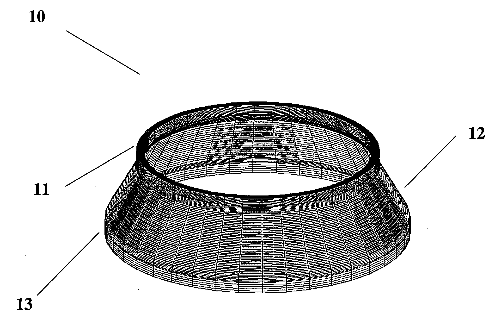
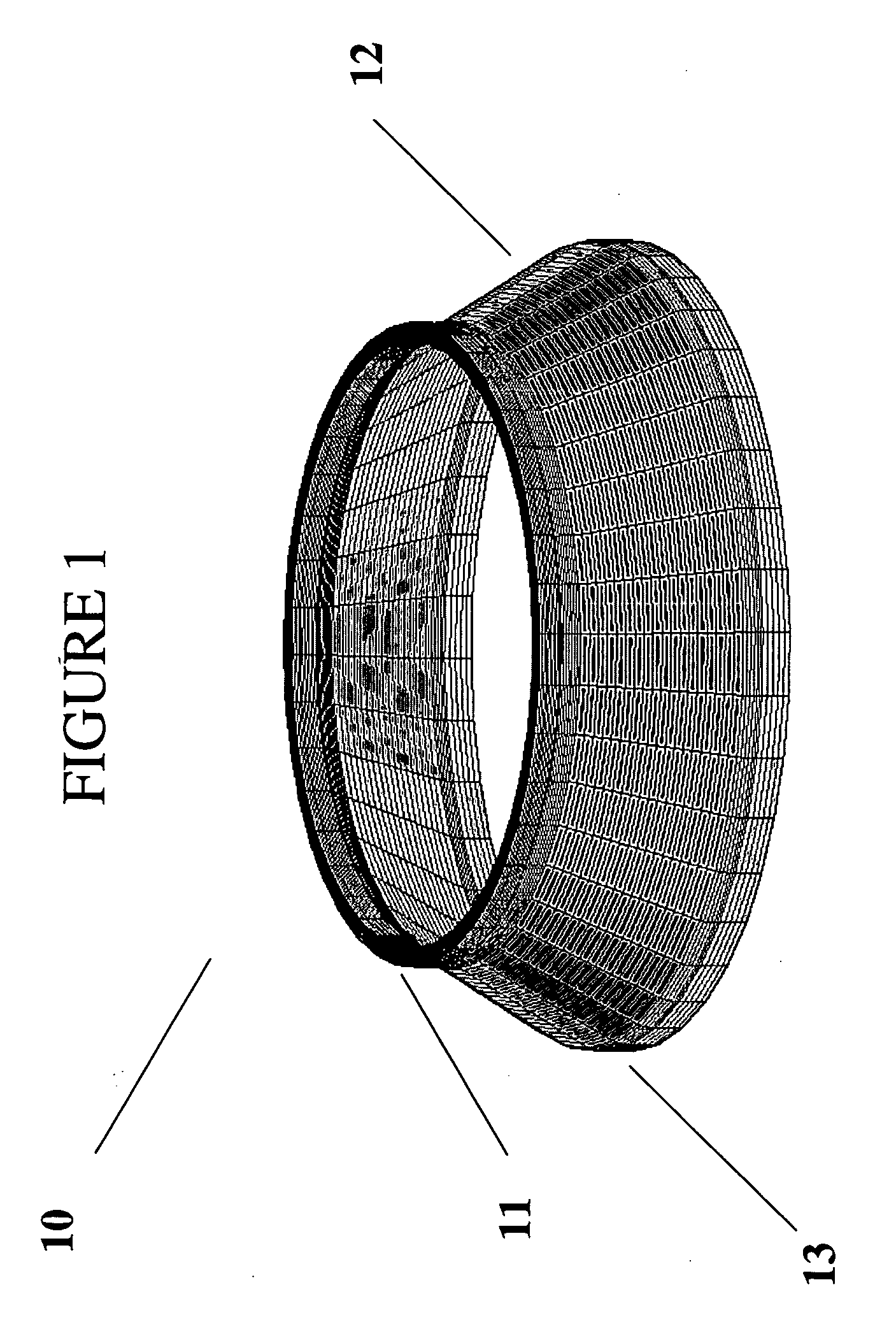
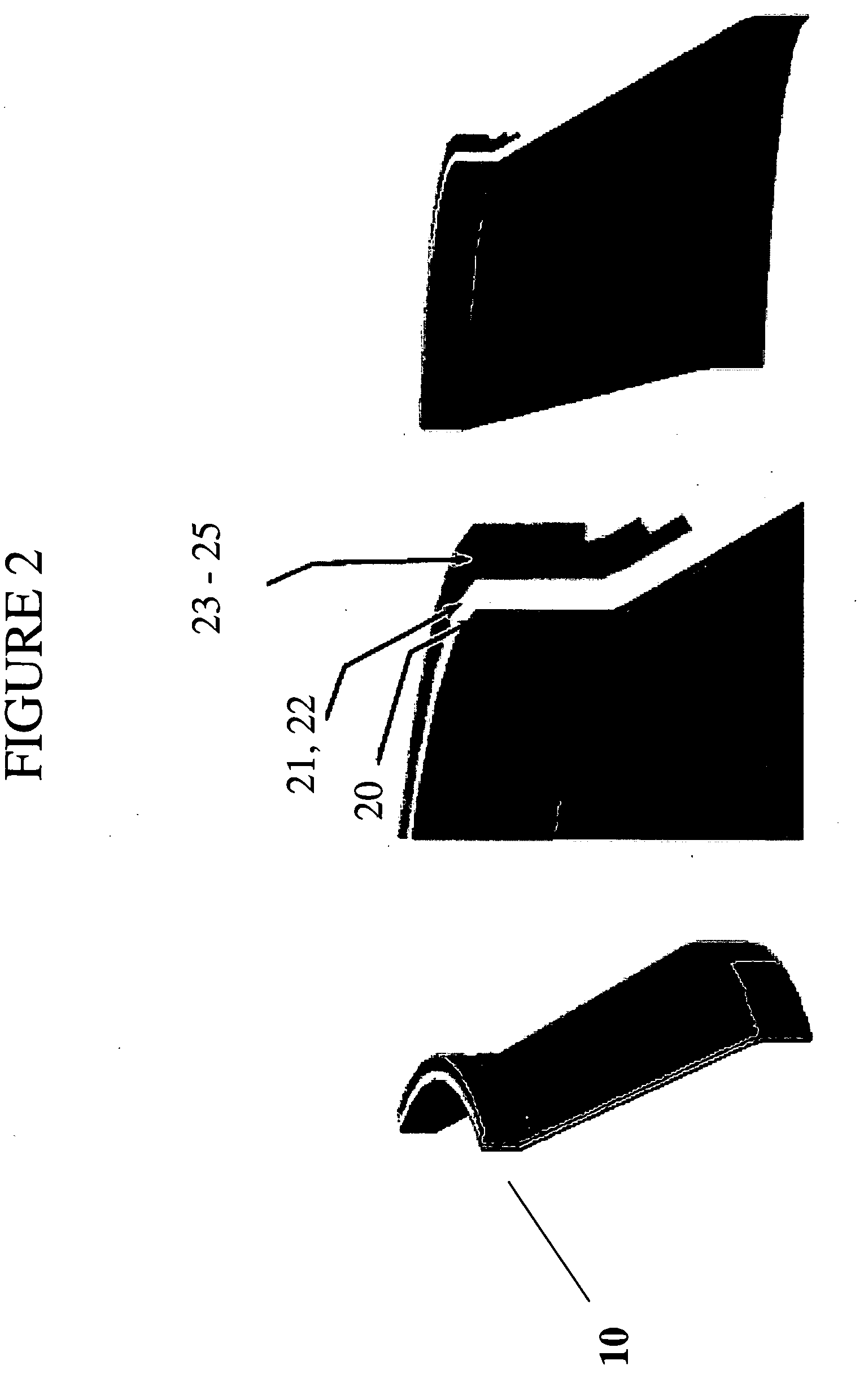
[0037]The instant composite hub and supportive components illustrated herein represent the fruits of a design effort pointed at development a flywheel energy storage system capable of achieving its maximum energy density, while being capable of repeated high peak-po...


PUM


Abstract

A flywheel energy storage system emphasizing enhancements developed for space applications including development of a flywheel rotor system capable of achieving maximum energy density, while being capable of repeated high peak-power demands. Illustrated is a rotor system comprising a composite hub, capable of supporting an optimized high-speed composite rim and shaft, working in combination with a switched reluctance motor.

Description

FIELD OF THE INVENTION[0001]The present invention relates generally to flywheel energy storage systems and particularly to enhancements developed for overall systems adapted for spacecraft applications including development of a flywheel energy storage system capable of achieving its maximum energy density, while being capable of repeated high peak-power demands, due to the design and development of a flywheel rotor system featuring a composite high-strain hub that would be capable of following a mass-optimized composite rim, while simultaneously satisfying the rotor-dynamic requirements of the active magnetic bearing.REFERENCES[0002]In general within the art, descriptions of flywheel energy storage systems and their various related elements can be found in U.S. Pat. Nos. 5,614,777 set forth by Bitterly et al; 567,595, 5,708,312, 5,770,909, and 58,644,303 by Rosen et al; 3,860,300 and 4,147,396 by Lyman; 3,791,704 and 4,088,379 by Perper; 5,627,419 by Miller; 4,910,449 by Hiyama et ...

Claims


Application Information

Patent Timeline
IPC IPC(8): F16F15/305H02K7/02
CPCF16F15/305Y10T74/212Y02E60/16H02K7/025
Inventor SPEARS, WARDPOLIMENO, MATTHEWANSBIGIAN, DAVIDHOCKNEY, RICHARD
Owner BEACON POWER LLC
Why Eureka
Try Eureka