
Negative electrode for secondary battery, secondary battery, and manufacturing methods thereof

Pending Publication Date: 2020-08-13
THE UNIV OF TOKYO
View PDF2 Cites 0 Cited by
  • Summary
  • Abstract
  • Description
  • Claims
  • Application Information

AI Technical Summary

Benefits of technology

This patent is about a new type of negative electrode for a battery and a battery that uses this electrode. The electrode is made with a silicon-based material that has a specific structure, including a region with lithium and small carbonate particles. This structure is created by a process where a voltage is applied to the material and pressure is applied through a liquid-permeable elastic body. This new electrode can increase the energy density and capacity of the battery, and it is efficient to manufacture. Overall, this patent provides a solution for creating a high-capacity secondary battery with a negative electrode that is durable and easy to produce.

Problems solved by technology

Nevertheless, the energy density of a lithium ion secondary battery is approaching a theoretical limit, and development of a new secondary battery that realizes an even higher energy density is required.
However, such Si compounds are reportedly problematic in having low charge-discharge efficiency during the initial stage of the charge-discharge cycle and thus a large irreversible capacity, and a large volume change associated with charging and discharging, readily resulting in deformation, and have not progressed in practical application.

Method used


Image

  • Negative electrode for secondary battery, secondary battery, and manufacturing methods thereof
  • Negative electrode for secondary battery, secondary battery, and manufacturing methods thereof
  • Negative electrode for secondary battery, secondary battery, and manufacturing methods thereof

Examples


example 1

(Preparation of Secondary Battery)

[0120]7.0 g of Si powder, 1.5 g of acetylene black, and 15 g of an aqueous solution of 10% sodium polyacrylate having an average molecular weight of 450,000 were weighed and kneaded while adding purified water and uniformly mixing to obtain a mixture. The viscosity was adjusted by further adding purified water to this mixture, and a negative electrode slurry for coating a negative electrode active material layer was prepared. This slurry was coated with a knife roll coater at a coating thickness of 100 μm and a width of 130 mm on a Cu foil having a thickness of 20 μm, and dried at 80° C. Subsequently, the coating was performed at a thickness of 30 μm on a Cu foil serving as a current collector by roll pressing. Through the forming step of such a negative electrode active material layer, a negative electrode in which the negative electrode active material layer 3′ having a gray color and Si as an active material is provided on the current collector 1...

example 2

(Preparation of Coated Negative Electrode 2-1)

[0130]A negative electrode ink for coating was prepared by weighing 7.0 g of Si powder, 1.5 g of acetylene black, and 15 g of an N-methyl pyrrolidone solution of 10% polyvinylidene fluoride having an average molecular weight of 50,000, and further adjusting the viscosity by adding N-methyl pyrrolidone. This ink was coated with a knife roll coater at a coating thickness of 100 μm and a width of 130 mm on a Cu foil having a thickness of 20 μm, and dried at 80° C. Subsequently, by roll pressing, a negative electrode active material layer having a thickness of 40 μm was formed on the Cu foil serving as the current collector to obtain a coated negative electrode 2-1 including Si as the active material and polyvinylidene fluoride as the binder.

(Preparation of Coated Negative Electrode 2-2)

[0131]A negative electrode ink for coating was prepared by weighing 7.0 g of Si powder, 1.5 g of acetylene black, and 5 g of an aqueous solution of 50% polya...

example 3

(Preparation of Secondary Battery)

[0138]7.5 g of rubeanic acid, 1.5 g of vapor-grown carbon fiber (VGCF), and 1.0 g of polytetrafluoroethylene resin binder were weighed and kneaded while adding purified water and uniformly mixing. The viscosity was adjusted by further adding ion exchange water to this mixture, and a slurry for coating a positive electrode was prepared. A positive electrode including rubeanic acid and VGCF was prepared by coating this slurry with a knife roll coater at a coating thickness of 100 μm and a width of 130 mm on an Al foil having a thickness of 20 μm, drying the coating at 80° C., and subsequently punching the material into a circular shape having a diameter of 12 mm.

[0139]The positive electrode prepared as described above was placed on a positive electrode case of a coin-type battery, and a 20-μm-thick separator composed of a porous polypropylene film was laminated thereon. Furthermore, a predoped Si negative electrode prepared by the same method as in Ex...


PUM


Abstract

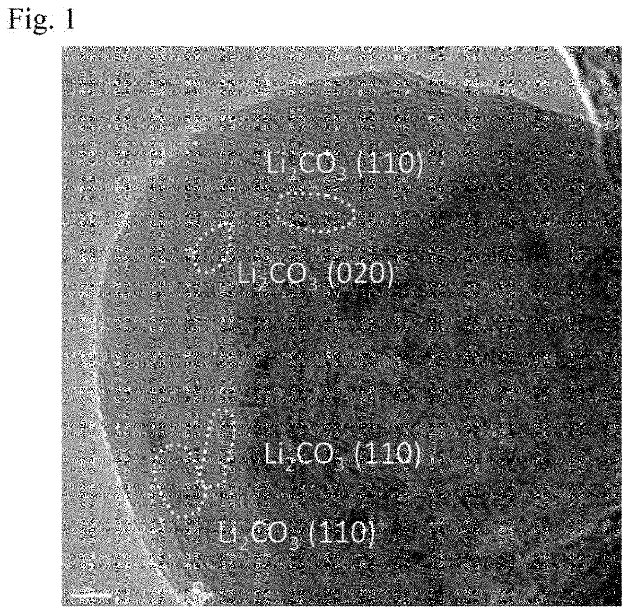
To provide a negative electrode for a secondary battery and a secondary battery having a large energy density and a capacity less likely to reduce even after repeated charging and discharging, and manufacturing methods thereof The above-described problem is solved by a negative electrode for a secondary battery (3) comprising a negative electrode active material layer (3′) including at least a silicon-based active material and a binder, and a negative electrode current collector (14) having a structural form in which the silicon-based active material has an amorphous region including lithium and island-shaped lithium carbonate is distributed in the amorphous region. This negative electrode for a secondary battery (3) is manufactured by a method including a step of forming a negative electrode active material layer (3′) including a Si-based active material and a binder, and a predoping step of bringing an electrolytic solution (5) containing Li into contact with the negative electrode active material layer (3′), applying pressure, and introducing Li ions by an electrochemical method.

Description

FIELD OF THE INVENTION[0001]The present invention relates to a negative electrode for a secondary battery, a secondary battery, and manufacturing methods thereof. More specifically, the present invention relates to a negative electrode for a secondary battery and a secondary battery which, by a predoping step of introducing Li ions into a negative electrode by an electrochemical method while applying pressure, has a large energy density and a capacity less likely to reduce even after repeated charging and discharging, and manufacturing methods thereof.BACKGROUND ART[0002]With the expansion of markets of mobile phones, portable electronic devices, and the like, batteries used for these devices are required to have higher energy density and higher output. In order to meet such requirements, a secondary battery has been developed that establishes an alkali metal ion such as Li as a charge carrier and utilizes an electrochemical reaction accompanying a charge transfer thereof. In partic...

Claims


Application Information

Patent Timeline
IPC IPC(8): H01M4/1395H01M4/62H01M4/04
CPCH01M4/0452H01M2004/021H01M2004/027H01M2004/028H01M4/622H01M4/1395H01M4/139H01M4/38H01M4/48H01M4/62Y02E60/10H01M4/0459H01M4/0445H01M4/134H01M4/386H01M10/052H01M4/0435C01B33/06
Inventor NISHIHARA, HIROSHIMIYACHI, MARIKOSATO, MASAHARU
Owner THE UNIV OF TOKYO
Learn More