Composite fuel permeation barrier seal

a fuel permeation barrier and composite technology, applied in the direction of engine seals, mechanical equipment, engine components, etc., can solve the problems of suspected permeation of fuel through certain seals/gaskets, measurably affecting the environment, etc., to reduce the emission of volatile organic compounds (vocs), reduce the deformation of the seal assembly, and minimize the effect of vapor and liquid passag

Inactive Publication Date: 2010-01-28
KENT JR EDWIN J +1
View PDF34 Cites 11 Cited by
  • Summary
  • Abstract
  • Description
  • Claims
  • Application Information

AI Technical Summary

Benefits of technology

[0006]One form of the present invention provides a novel seal assembly. The seal assembly is adapted to be positioned between two opposing sealing members of selected components which, when joined together, can contain or convey an organic compound. In preferred embodiments, the seal assembly comprises the first sealing portion or member formed from an elastomeric material. The first member is adapted to bear against at least one and preferably both of the opposing sealing surfaces. The seal assembly also comprises a second sealing portion or member, secured to the first sealing portion and adapted to bear against at least one of the opposing sealing members. The second sealing portion can be formed of a fuel permeation-resistant material. Preferably the first and second sealing portions are connected via a mechanical interlock connection to provide the seal assembly or composite. In selected embodiments, the first and second sealing portions also can be over-laminated and / or bonded together with adhesive or a tie member. In preferred embodiments, the seal assembly significantly reduces emission of volatile organic compounds (VOCs).
[0007]The seal assembly is compressible and, when positioned between the sealing members, can deform as the system components are connected together. The second portion can be formed of a compression limiting material. Consequently, the second portion of the seal assembly can limit the deformation of the seal assembly between the sealing members and / or minimize vapor and liquid passage around the permeation-resistant portion.
[0013]In other forms, the present invention provides a method for reducing emission of volatile organic compounds. The method includes providing an organic vapor permeation barrier interconnected with a first sealing portion formed of an elastomeric material. In preferred embodiments, the fuel vapor permeation barrier is formed of a compression-limiting material. In other embodiments, the fuel vapor barrier is formed of metallic material or a fluorocarbon resin. In preferred embodiments, the permeation barrier is adapted to reduce and / or eliminate fuel permeation through the seal assembly.

Problems solved by technology

While current technology effectively seals the fuel system components from liquid fuel leaks, fuel is suspected to permeate through certain seals / gaskets, albeit in minute amounts.
While the actual quantity of fuel emitted per vehicle at any one time may be small, the large number of vehicles in use and the continuous emission of fuel vapor from the seals / gaskets over the lifetime of the vehicle suggests that this may measurably impact the environment.

Method used


Image

  • Composite fuel permeation barrier seal
  • Composite fuel permeation barrier seal
  • Composite fuel permeation barrier seal

Examples


Embodiment Construction

[0025]For the purposes of promoting and understanding the principles of the invention, reference will now be made to the embodiments illustrated herein, and specific language will be used to describe the same. It will nevertheless be understood that no limitation of the scope of the invention is thereby intended. Any alterations and further modifications in the described seals assemblies, devices, and / or methods, and any further applications of the principles of the invention as described herein, are contemplated as would normally occur to one skilled in the art to which the invention relates.

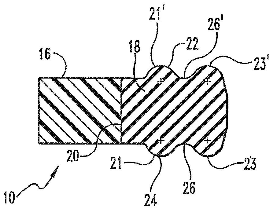
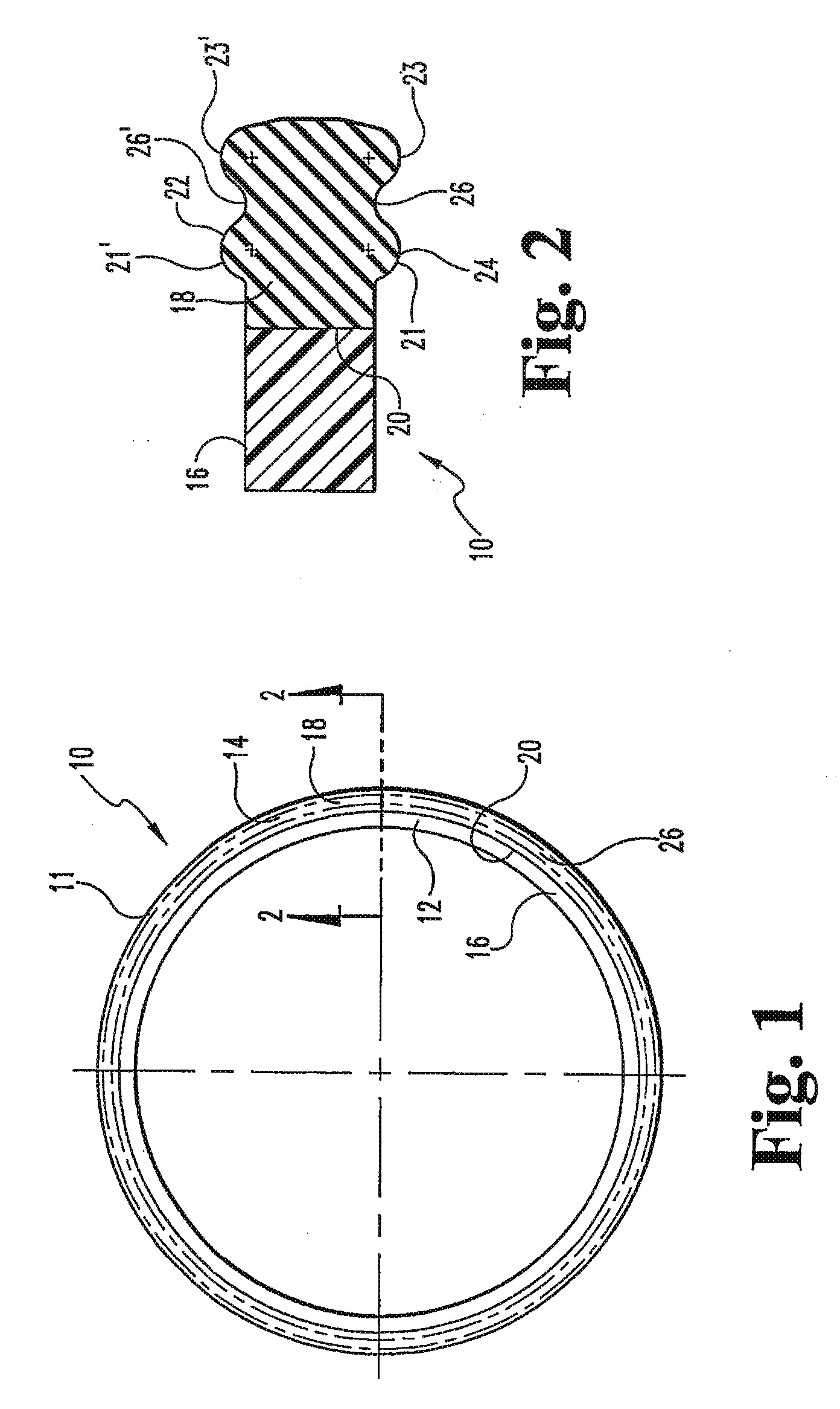
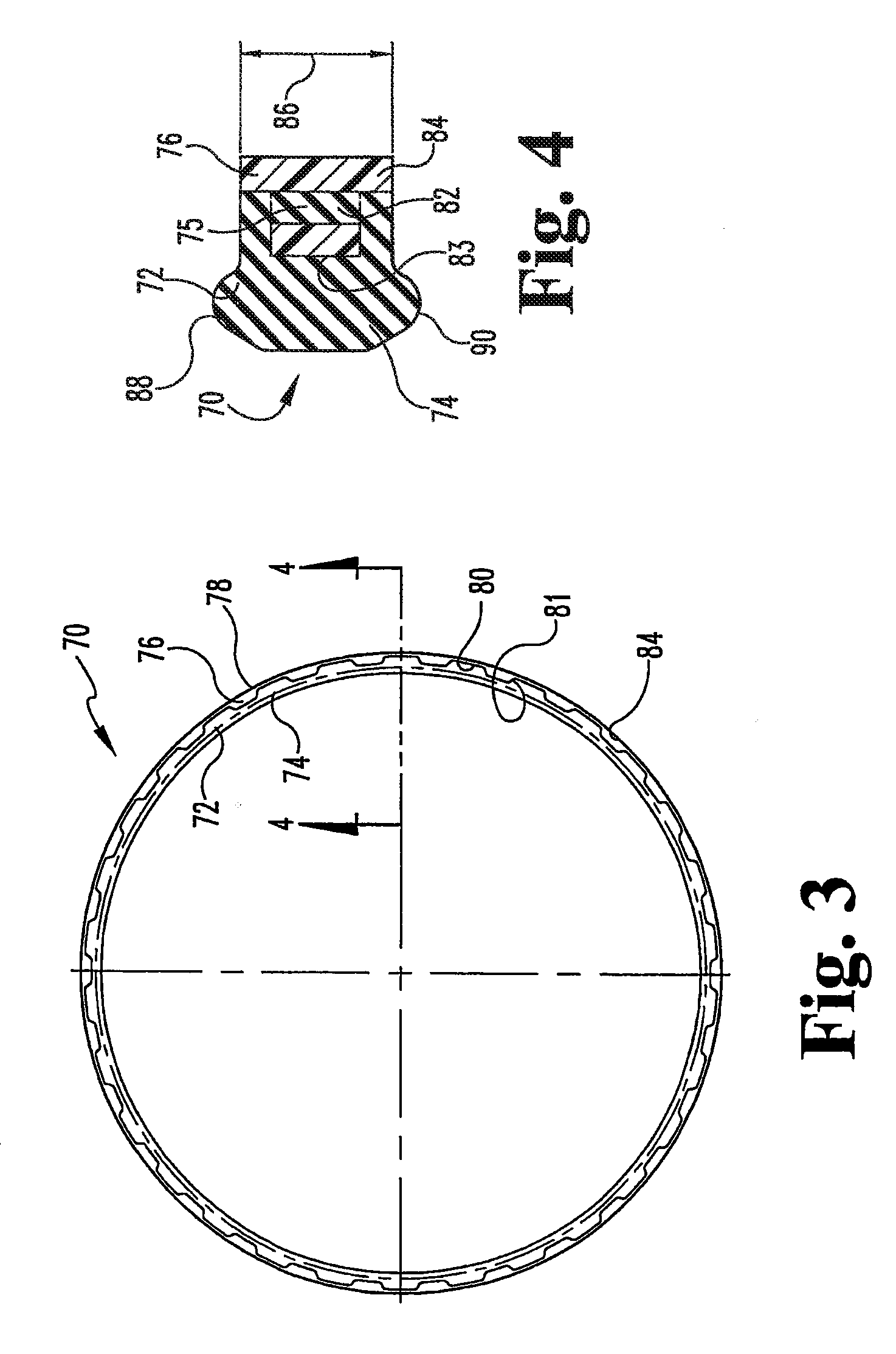
[0026]In general, the present invention provides a seal assembly that includes at least two barriers or sealing portions. The two sealing portions are connected together to form a composite seal or seal assembly. One or both of the sealing portions bear against the opposing sealing members of containment or delivery system components. In preferred embodiments, the first sealing portion can inhi...


PUM


Abstract

Composite seal or gasket for inhibiting the release of a volatile organic compound such as fuel. The seal includes a deformable portion interconnected to a vapor barrier portion via a mechanical or adhesive interlocking connection. The deformable portion can be formed from an elastomeric material. The vapor barrier portion can be formed from a wide variety of materials that inhibit permeation of the organic vapor. Examples of the materials for the vapor barrier include ductile metals, plastic polymers, and fluoroplastic polymers. The gaskets and seals can be, but are not restricted to be, used between the connections of the components in an automotive or consumer product fuel system.

Description

CROSS-REFERENCE TO RELATED APPLICATIONS[0001]The present application is a divisional of U.S. patent application Ser. No. 11 / 533,553, filed Sep. 20, 2006, which is a divisional of U.S. patent application Ser. No. 10 / 486,746, filed Jun. 16, 2005, which claims the benefit of the filing date of U.S. Provisional Application Ser. No. 60 / 312,837, filed Aug. 16, 2001, the disclosure of each of which is expressly incorporated herein by reference.BACKGROUND OF THE INVENTION[0002]In general this invention relates to seals and / or gaskets. More specifically, the present invention is directed to seals or gaskets for use with and between components to contain, store, and deliver volatile organic compounds, such as hydrocarbon-based fuels.[0003]There is an increased public awareness of the environmental harm associated with the release and / or emission of volatile organic compounds such as fuel into the atmosphere. For example, recent studies have expressed concern over the potential emission of fue...

Claims


Application Information

Patent Timeline
Patent Type & Authority Applications(United States)
IPC IPC(8): F16J15/02F16J15/06F16J15/10F16J15/12F16J15/32
CPCF16J15/064F16J15/3236F16J15/127F16J15/104
Inventor KENT, JR., EDWIN J.PEDDLE, DARRON G.
Owner KENT JR EDWIN J
Why Eureka
Try Eureka