Unburied Hydraulic Door Hinge System

a technology of hydraulic hinges and hinges, which is applied in the direction of door/window fittings, multi-purpose tools, construction, etc., can solve the problems of annoying installation of automatic closing doors, low efficiency of installation and repair, so as to achieve convenient installation and repair, fast and easy separation, and easy access

Inactive Publication Date: 2010-02-04
OH SE JIN +1
View PDF12 Cites 51 Cited by
  • Summary
  • Abstract
  • Description
  • Claims
  • Application Information

AI Technical Summary

Benefits of technology

[0019]Since the unburied hydraulic hinge system with the above mentioned figures in accordance with the present invention is formed on the bottom corner of the door, it does not damage the aesthetic appearance of a transparent glass door such as a reinforced glass door and is very easy to install and repair because it is not buried. From the maintenance point of view, the user can easily access it because the split-type mounting plates can be fast and easily separated. The hydraulic cylinder and the rotating drive mechanism, having a simplified structure and operation, not only improve the durability and the lifespan of the hydraulic hinge system but also provide the possibility of mass production as well as production cost saving. Consequently, the present invention has high economic efficiency.

Problems solved by technology

When a door is left open after a passerby has passed through it, lots of energy loss would occur as a result of the wasted work of an air-conditioning / heating system of a room, and indoor environments can be made inferior due to the inflow of polluted air or dust from the outside.
However, in the conventional automatic closing door formed with the above mentioned figures, there is a problem in that the installation of the automatic closing door is annoying because the space for the hydraulic hinge needs to be secured first on the floor where the door will be installed before the hydraulic hinge can be installed therein.
Moreover, the structure of the conventional automatic closing door is complicated since the hydraulic hinge and the cylinder are formed outside of the frame.
And the maintenance / repair work is difficult to do because the cylinder works separately from the door.
Especially, the automatically closing door with the conventional hydraulic hinge of the related art is uneconomical since the maintenance / repair job costs a lot to perform because of the vulnerable structural strength and durability resulting from the use of the loose spring of the hinge and the leakage of the oil pressure and the like, according to the increasing opening / closing of the door.
When it needs to be installed on a generally used reinforced glass door, the esthetic appearance of the reinforced glass door is sharply declined and the elegant design is damaged due to the base frame being installed with the hydraulic hinge.
Because the whole bottom portion of the general door needs to be cut to install the base frame formed with the hydraulic hinge, the use of the standardized door is not possible and it is highly inefficient from the general-purpose and production points of view.
In the automatic closing door with the frame for the insertion of the hydraulic hinge as above mentioned, when the hydraulic hinge is not working properly or needs to be repaired for the maintenance, it is very difficult for the workman to gain access thereto since the cylinder member and drive member of the hydraulic hinge system should be disassembled and repaired only after the whole base frame has been removed from the door.
Further, since the hydraulic cylinder, the hinge axle member interlocked with the hydraulic cylinder, and the drive members are linked in a complicated manner with so many complex parts, they are the main causes of increased production cost together with the associated economic burden from the high production cost, and inefficiency of the mass production.
Its durability is too short because the risks of malfunction or breakdown can be increased due to the many numbers of linked parts as well as the decreased easy assemblability of them.

Method used


Image

  • Unburied Hydraulic Door Hinge System
  • Unburied Hydraulic Door Hinge System
  • Unburied Hydraulic Door Hinge System

Examples


Embodiment Construction

[0028]Reference will now be made in greater detail to an exemplary embodiment of the invention, which is illustrated in the accompanying drawings.

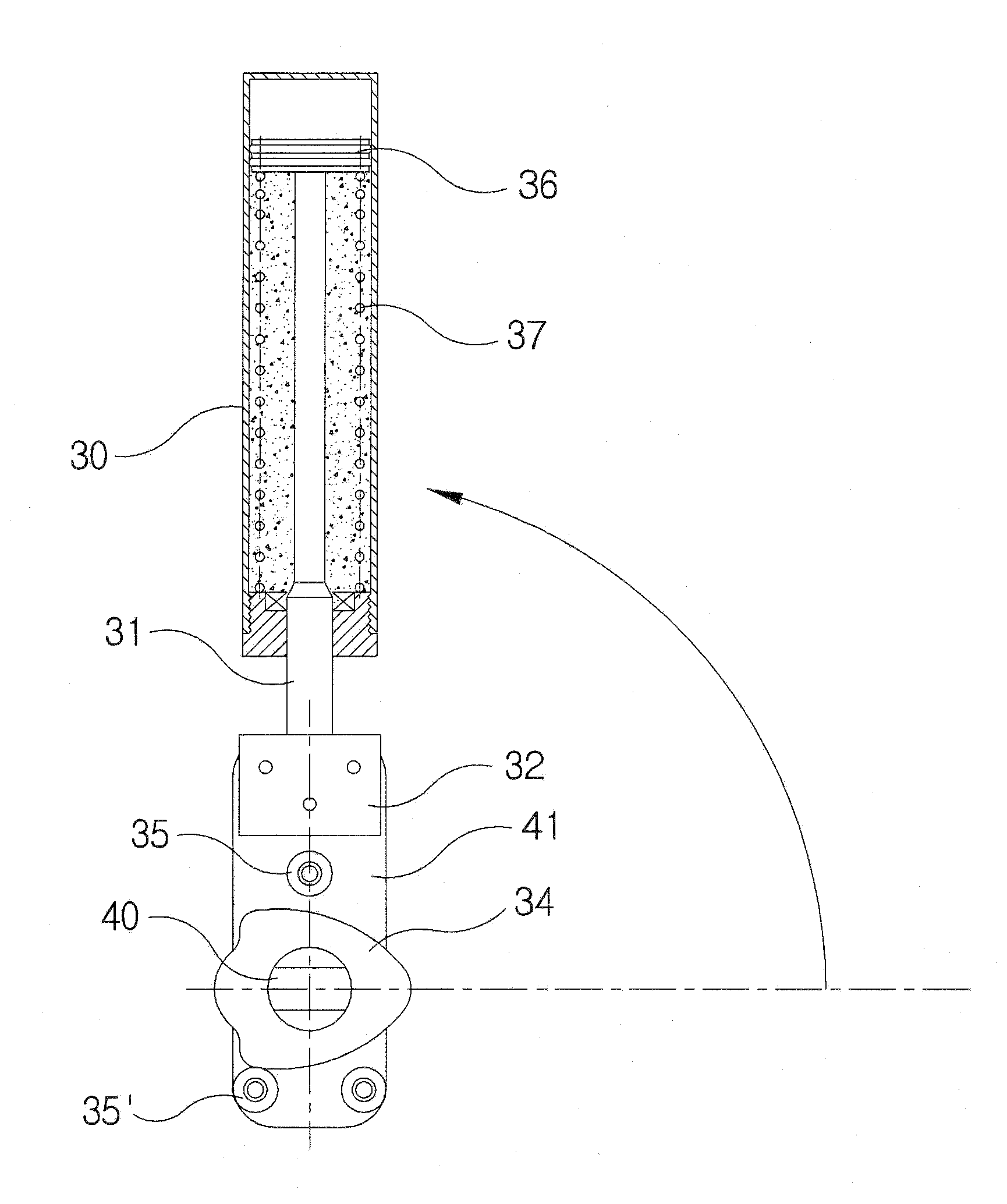
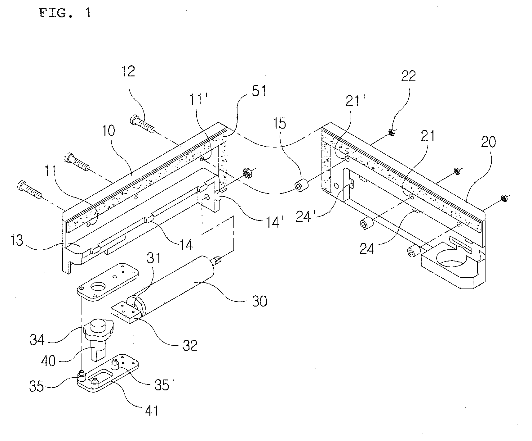
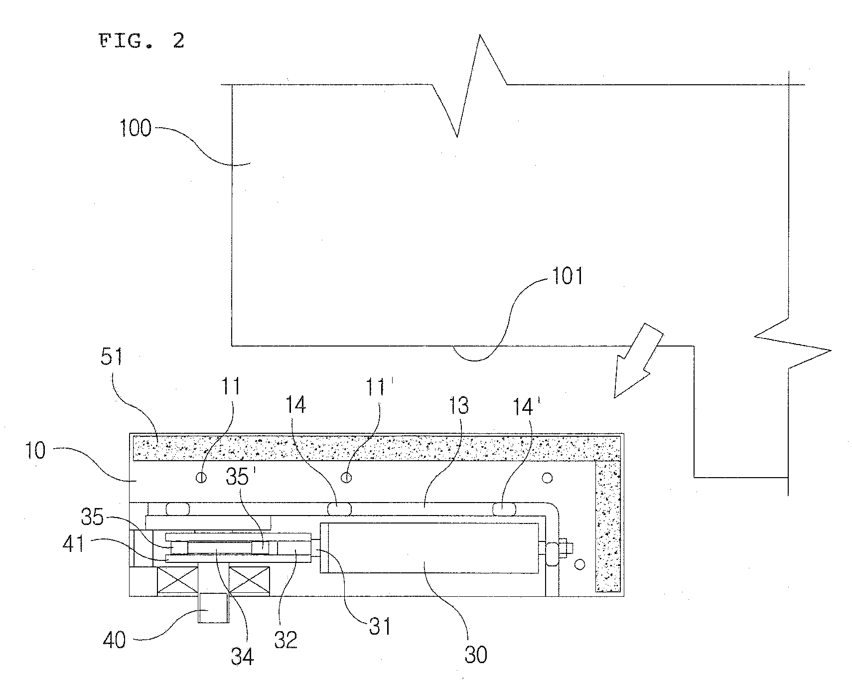
[0029]FIG. 1 is an exploded diagram of the hydraulic hinge system in accordance with the present invention; FIG. 2 is a cross-sectional view showing a bottom corner of a door with the hydraulic hinge system in accordance with the present invention; and FIG. 3 is a cross-sectional view showing the hydraulic hinge system in accordance with the present invention.

[0030]As illustrated in the drawings, a hydraulic hinge system in accordance with the present invention can be installed on one bottom corner of a general door by coupling a first mounting plate 10 with a second mounting plate 20, which are of the split-type, and a carved portion needs to be formed at the bottom corner of the door 100 where the hydraulic hinge system will be installed. In the prior art, a frame structure was formed by cutting the whole bottom portion of the door. Howe...


PUM


Abstract

An unburied hydraulic door hinge system for automatically closing a door is directly mounted on a bottom corner of a door. Since the unburied hydraulic hinge system can be installed on the bottom corner of the door, it does not damage the aesthetic appearance of a transparent glass door such as a reinforced glass door, and is very easy to install and repair because it is not buried. From the maintenance point of view, the worker can easily gain access thereto because the split-type mounting plates can be quickly and easily separated. A hydraulic cylinder and a rotating drive mechanism, having a simplified structure and operation, not only improve the durability and lifespan of the hydraulic hinge system but also provide the possibility of mass production as well as production cost saving. Consequently, the hydraulic door hinge system has high economical efficiency.

Description

BACKGROUND OF THE INVENTION[0001]1. Field of the Invention[0002]The present invention relates to a hydraulic hinge system for an automatically closing door, and more particularly, to an unburied hydraulic door hinge system directly mounted on the automatic closing door, wherein the opened door is automatically closed by the hydraulic expansion of a hydraulic cylinder, caused by a mounting plate installed at the bottom corner of the door, as well as by the compressive action of the hydraulic cylinder in the hinge system according to the status of the opened door.[0003]2. Description of the Related Art[0004]When a door is left open after a passerby has passed through it, lots of energy loss would occur as a result of the wasted work of an air-conditioning / heating system of a room, and indoor environments can be made inferior due to the inflow of polluted air or dust from the outside.[0005]A hydraulic hinge for an automatic closing door has been developed and installed to solve these k...

Claims


Application Information

Patent Timeline
Patent Type & Authority Applications(United States)
IPC IPC(8): E05F3/20
CPCE05D5/0246E05F3/104E05F5/00Y10T16/2771E05Y2600/46E05Y2900/132E05D7/081E05Y2201/21E05F3/04E05F3/20
Inventor OH, SE JINOH, GUM SUNG
Owner OH SE JIN
Why Eureka
Try Eureka