Fuel supply pump

a technology of fuel supply and pump, which is applied in the direction of pump, positive displacement liquid engine, machine/engine, etc., can solve the problems of limiting the increase of the pressure receiving area, limiting the structural width of the supporting wall to which the above-described reaction force is applied, and causing damage such as seizure to the axial end parts. , to achieve the effect of reducing the face pressure, preventing seizure, and high pressure injection

Active Publication Date: 2010-02-04
DENSO CORP
View PDF14 Cites 24 Cited by
  • Summary
  • Abstract
  • Description
  • Claims
  • Application Information

AI Technical Summary

Benefits of technology

[0011]The present invention addresses the above disadvantages. Thus, it is an objective of the present invention to provide a fuel supply pump which achieves a good balance between reduction in face pressure as a countermeasure against high pressurization of injection pressure and prevention of seizure at an end portion and end face of a roller even if acting force which is different from a direction of linear motion is applied to the roller.

Problems solved by technology

However, according to the conventional technology of JP-A-08-14140, a pressure receiving width of the axial end parts and the supporting wall to which the above-described reaction force is applied is structurally limited to the supporting wall that is a side wall of the tappet body, which accommodates the roller, except the roller.
In the conventional technology having such a structure, when the above injection pressure is more highly pressurized, a face pressure at the axial end parts of the roller pin exceeds a face pressure acceptable value, so that there is concern that damage such as seizure may be caused to the axial end parts.
However, a diameter of the roller pin is increased to a roller diameter or less, and even if the diameter of the roller pin is increased to the roller diameter, there is a limit to the increase in the pressure receiving area as a result of the product of the diameter of the roller pin and the pressure receiving width.
In expanding the pressure receiving width, for example, because the tappet is upsized, there is concern that costs of the fuel supply pump may increase or installability of the pump in an engine may be limited.
That is, it has been found that, although face pressure is reduced since an outer circumferential surface of a columnar roller is in sliding contact with a sliding contact surface of a tappet body, a corner portion of axial end part of the roller and a side wall of the cylindrical tappet body may be brought into contact with each other, thereby causing seizure.
Moreover, by reason of, for example, variation in alignment between the roller and the cam, force in a direction perpendicular to a direction of rectilinear motion of the tappet, i.e., in a thrust direction of the roller, is sometimes applied to the roller, so that there is concern that the above-described possibility may increase.

Method used


Image

  • Fuel supply pump
  • Fuel supply pump
  • Fuel supply pump

Examples


first embodiment

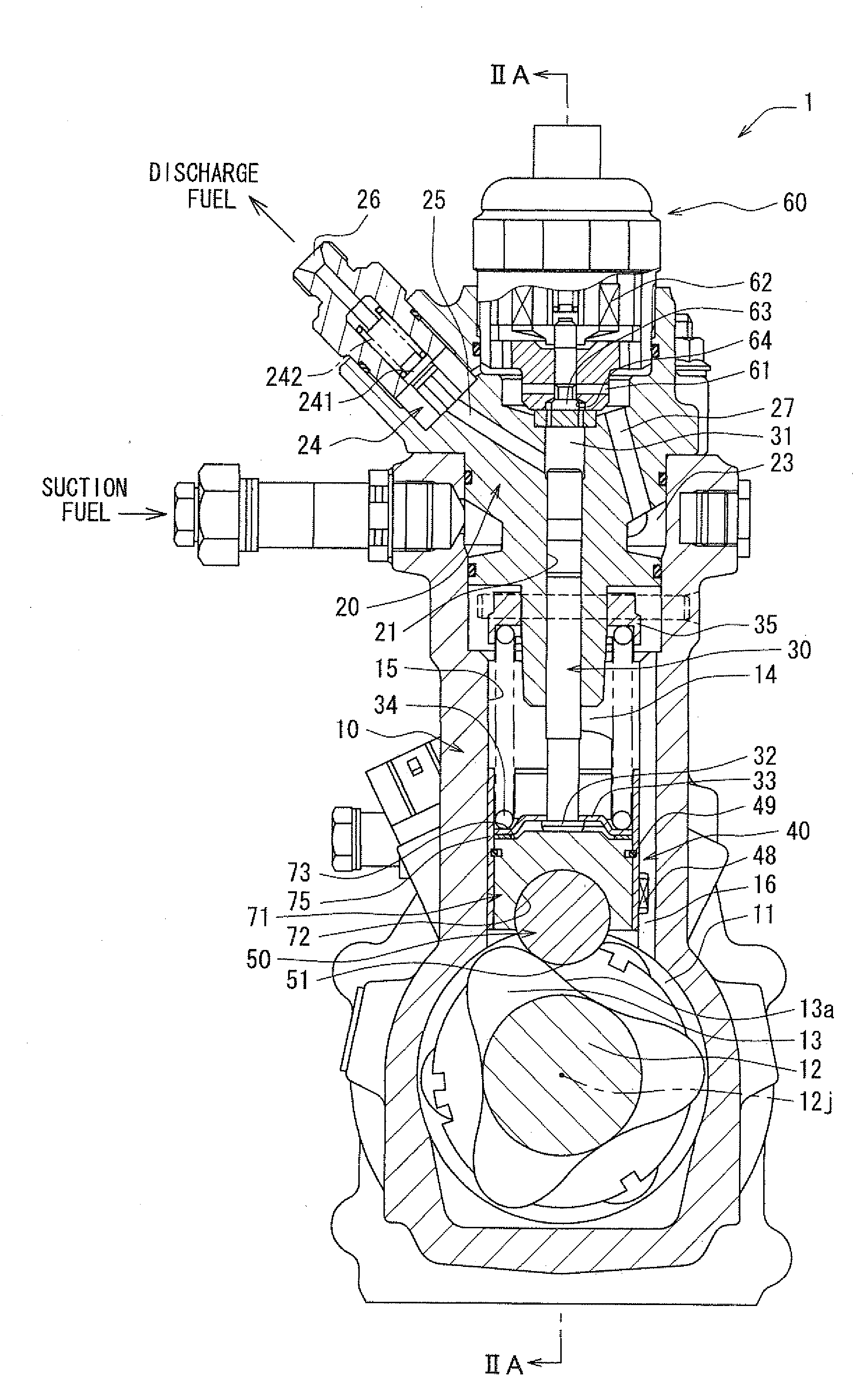
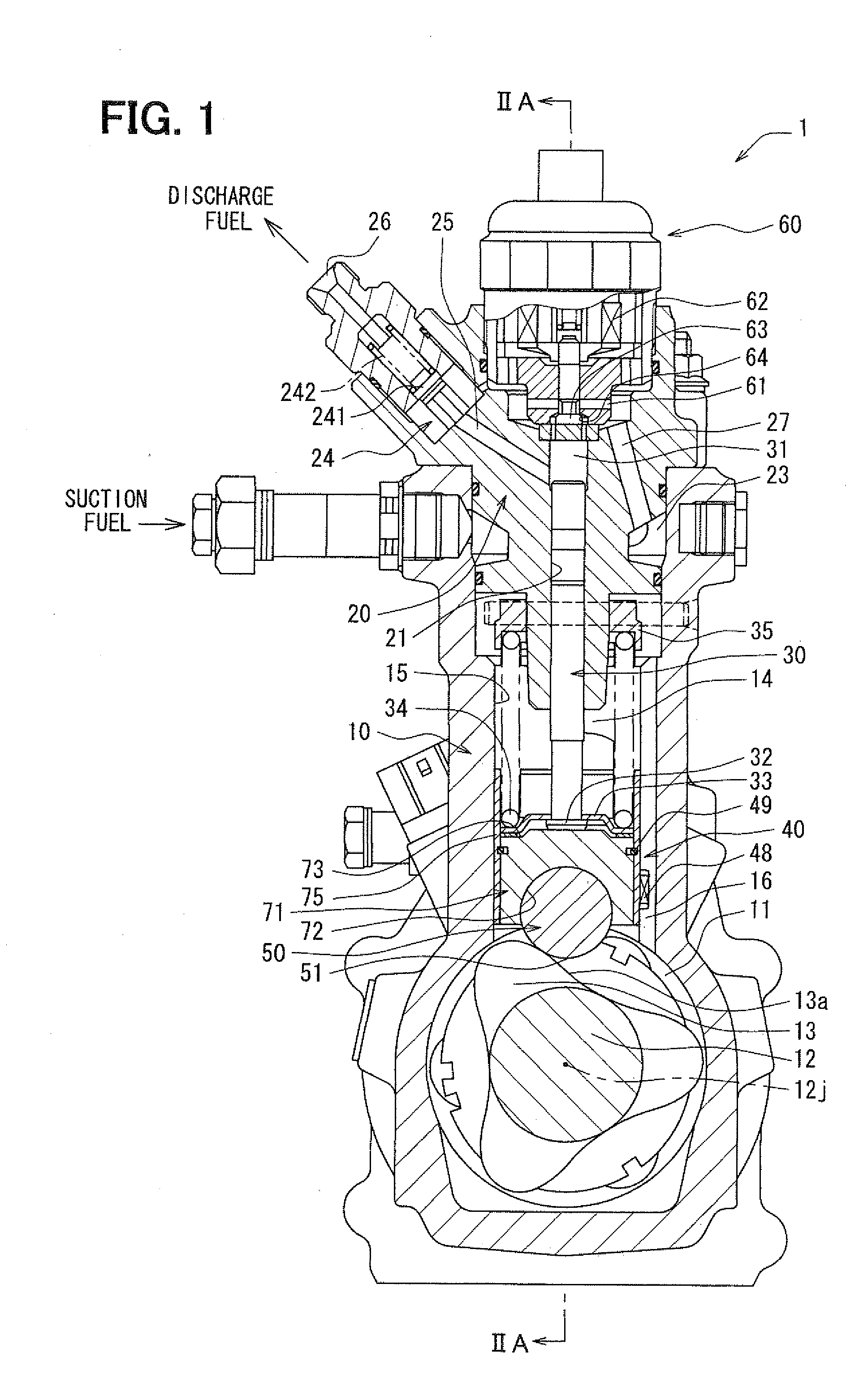
[0025]FIG. 1 to FIG. 3 illustrate application of a fuel supply pump according to a first embodiment of the invention to a fuel supply pump used in a common-rail type fuel injection system for a vehicle. The common-rail type fuel injection system includes mainly a fuel tank, a fuel supply pump 1, and a common rail and a fuel injection valve, which are not shown. The common-rail type fuel injection system accumulates pressure of high pressure fuel supplied through the fuel supply pump 1 in the common rail, and distributes high pressure fuel in the common rail to the fuel injection valve provided for each cylinder of an internal combustion engine, so as to inject and supply fuel into a combustion chamber of the cylinder. The fuel tank and the fuel supply pump 1 constitute a fuel supply system which supplies high pressure fuel to the common rail and the fuel injection valve.

[0026]The above described fuel tank stores fuel of normal pressure, and the fuel supply pump 1 draws fuel of norma...

second embodiment

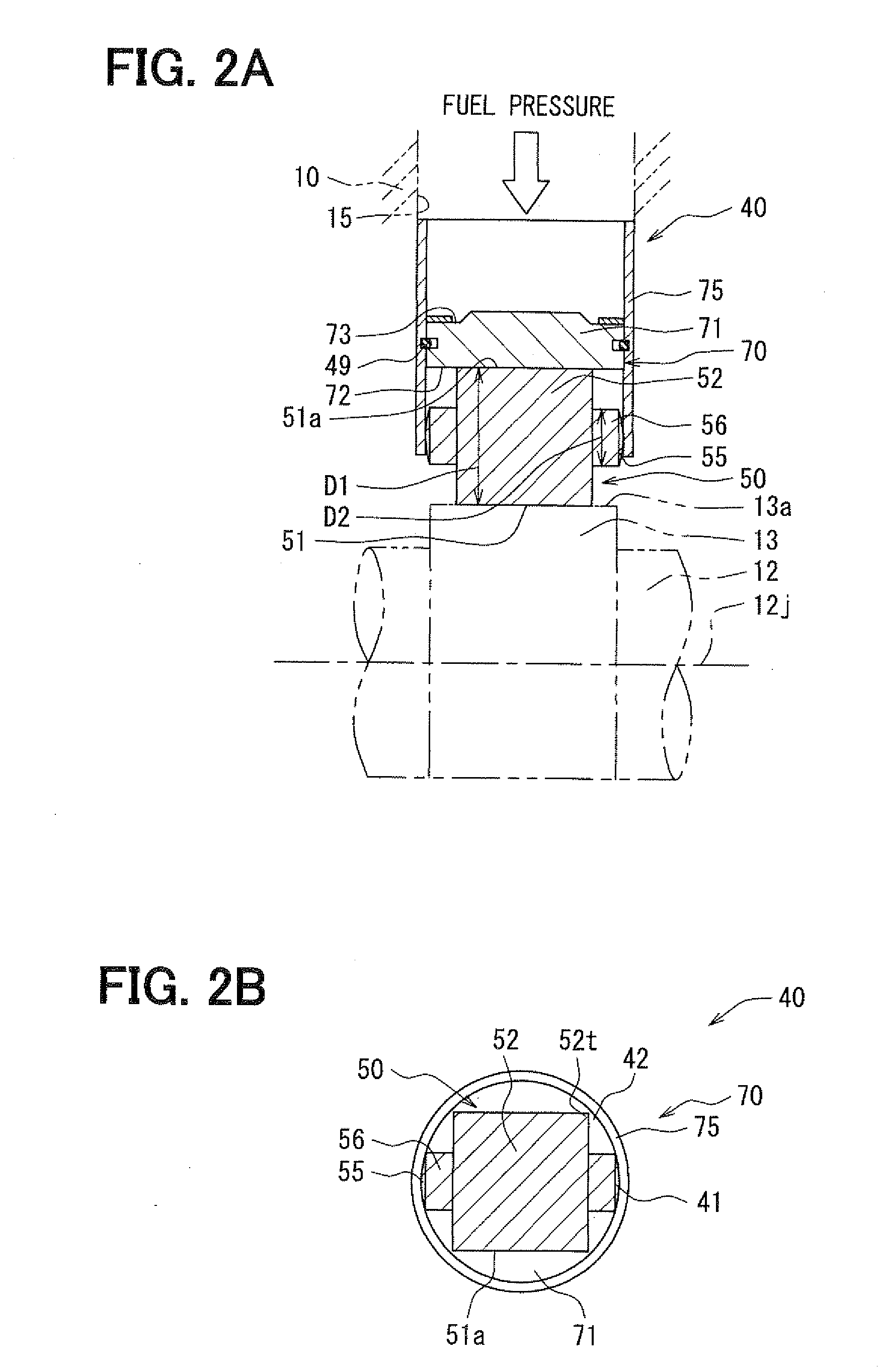
[0063]A second embodiment of the invention is illustrated in FIG. 4A and FIG. 4B. The second embodiment is a modification of the first embodiment. An example, in which a tapered part 53 is formed between a middle section 52 and a contact part 55 in a roller 50, is shown in the second embodiment.

[0064]As shown in FIG. 4A and FIG. 4B, the contact part 55 has a smaller diameter 92 than a diameter D1 of the middle section 52, and the tapered part 53 which continuously connects the middle section 52 and the smaller diameter D2 is formed between the middle section 52 and the contact part 55 in the roller 50.

[0065]In other words, since the tapered part 53, which continuously connects the middle section 52 and the smaller diameter D2, serves as a component between the middle section 52 and the contact part 55 in the roller 50, a corner part 54 which connects the middle section 52 and the tapered part 53 is formed to have an obtuse angle. Thus, the corner part 54 is shaped such that generati...


PUM


Abstract

A fuel supply pump includes a housing, a shaft in a case, a cam in the case formed eccentrically with respect to the shaft to rotate with the shaft, a tappet on an outer circumferential side of the cam movable in a vertical direction, and a plunger reciprocating with the tappet to pressurize fuel in a chamber. The tappet includes a roller and a supporting member rotatably supporting the roller in its thrust direction. The roller slidingly contacts outer circumference of the cam. The member includes an end face supporting the plunger, a surface at its end on an opposite side from the face and slidingly contacting outer circumference of the roller, and an inner wall supporting the roller in the thrust direction. The roller includes a middle section slidingly contacting the surface along its longitudinal direction, and a contact part at both ends of the section contacting the wall.

Description

CROSS REFERENCE TO RELATED APPLICATION[0001]This application is based on and incorporates herein by reference Japanese Patent Application No. 2008-200056 filed on Aug. 1, 2008.BACKGROUND OF THE INVENTION[0002]1. Field of the Invention[0003]The present invention relates to a fuel supply pump, and is suitable for application to, for example, a fuel supply pump, which pressure-feeds fuel under pressure equivalent to a fuel injection pressure in a fuel injection system of a diesel engine.[0004]2. Description of Related Art[0005]Conventionally, a pump which includes a cam that rotates upon application of driving force of an engine or the like, a plunger that reciprocates inside a pressurizing chamber, and a tappet that is provided between the cam and the plunger to convert rotary motion of the cam into rectilinear motion of the plunger, and which pressurizes fuel suctioned into the pressurizing chamber by the plunger that reciprocates as a result of the rotation of the cam, is known as a...

Claims


Application Information

Patent Timeline
Patent Type & Authority Applications(United States)
IPC IPC(8): F02M37/04F04B35/00
CPCF02M37/043F02M37/08F04B1/0439Y10T74/2107
Inventor MAKITA, YOSHIKAZU
Owner DENSO CORP
Why Eureka
Try Eureka