Fuel injection pump

a technology of fuel injection pump and stopper surface, which is applied in the direction of machines/engines, liquid fuel engines, positive displacement liquid engines, etc., can solve the problems of limited frictional wear of the disk shaped member and the stopper surface, and so as to prolong the life of the stopper surface, the effect of limiting the backrush

Inactive Publication Date: 2005-02-01
DENSO CORP
View PDF9 Cites 7 Cited by
  • Summary
  • Abstract
  • Description
  • Claims
  • Application Information

AI Technical Summary

Benefits of technology

It is another object to provide a fuel injection pump in which an adjustment for restricting an axial movement of the camshaft is easy.
It is preferable that an outer diameter of the disk shaped member is larger than that of the cam. With this construction, an area where the disk shaped member and the stopper are in slidable contact with each other becomes larger, compared with an area where the cam and the stopper surface are in slidable contact with each other. Accordingly, face pressure on portions of the disk shaped member and the stopper surface in contact with each other becomes lower. Further, as the disk shaped member is arranged in the same axis to the camshaft, contacting regions of the disk shaped member and the stopper are always the same. Accordingly, frictional wear of the disk shaped member and the stopper surface are limited and lifetimes thereof are prolonged.
It is preferable that a helical gear coaxially rotatable with the camshaft receives a driving force for driving the camshaft. The helical gear serves to limit a backrush generated when the cam drives a moving member so that the driving force applied to the moving member becomes even. Further, the helical gear acts as the biasing means for biasing the camshaft in the one axial direction thereof. As a result, it is not necessary to employ separately a biasing means such as a spring.
When an axial distance of a space where the disk shaped member is housed is too narrow, the disk shaped member is held by walls on opposite sides of the space and frictional wear is accelerated. On the other hand, when the axial distance of the space is too large, the camshaft often moves in an opposite direction to the axial biasing direction so that hammer noises are likely to occur. Therefore, prefererably, the disk shaped member is housed in advance in a space provided axially between first and second connecting members which are separate bodies from the housing. The axial distance of the space is easily adjusted before the camshaft is assembled to the housing, for example, by screwing the second connecting member into the first connecting member.

Problems solved by technology

Accordingly, frictional wear of the disk shaped member and the stopper surface are limited and lifetimes thereof are prolonged.

Method used


Image

  • Fuel injection pump
  • Fuel injection pump
  • Fuel injection pump

Examples


first embodiment

(First Embodiment)

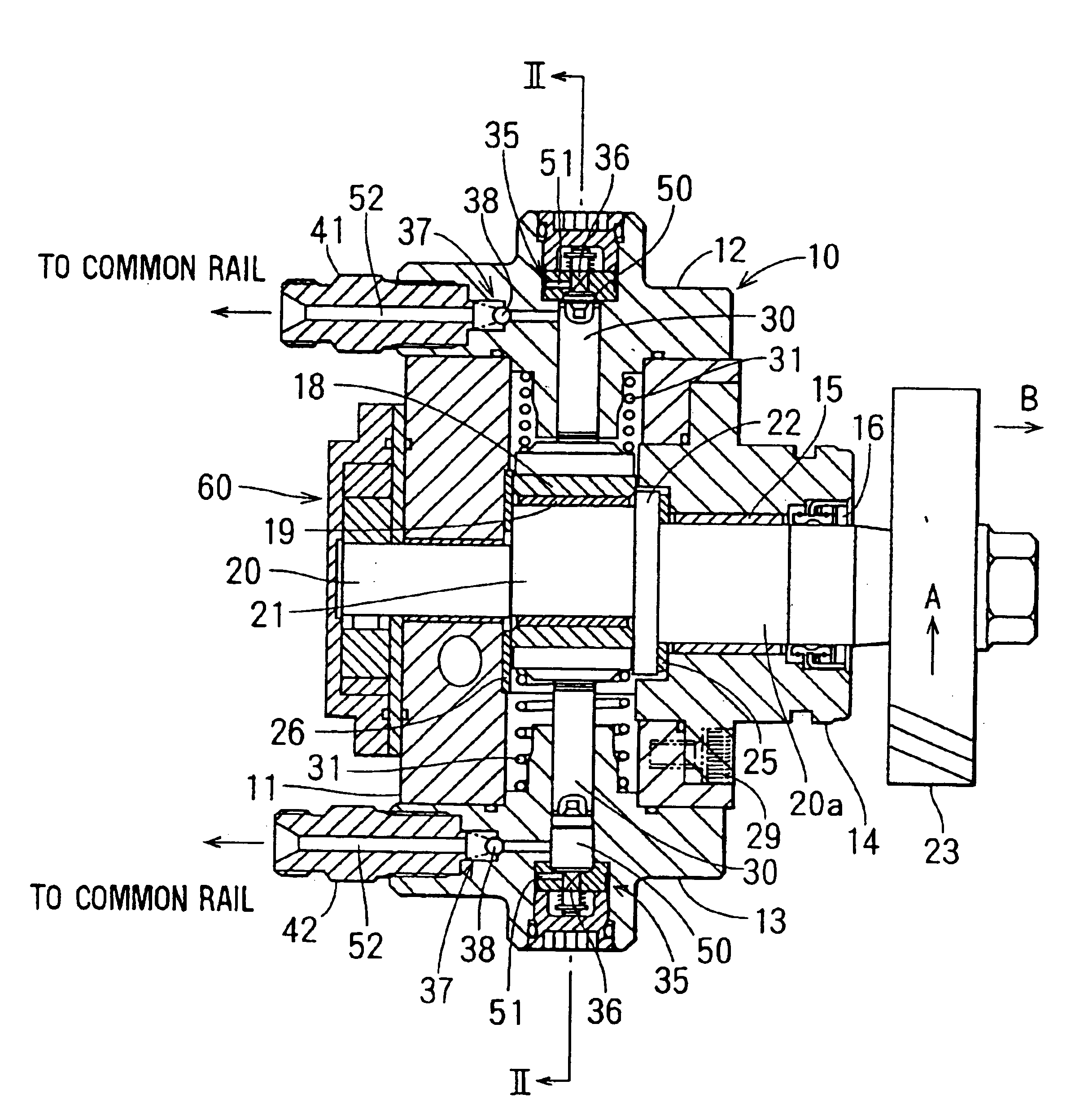
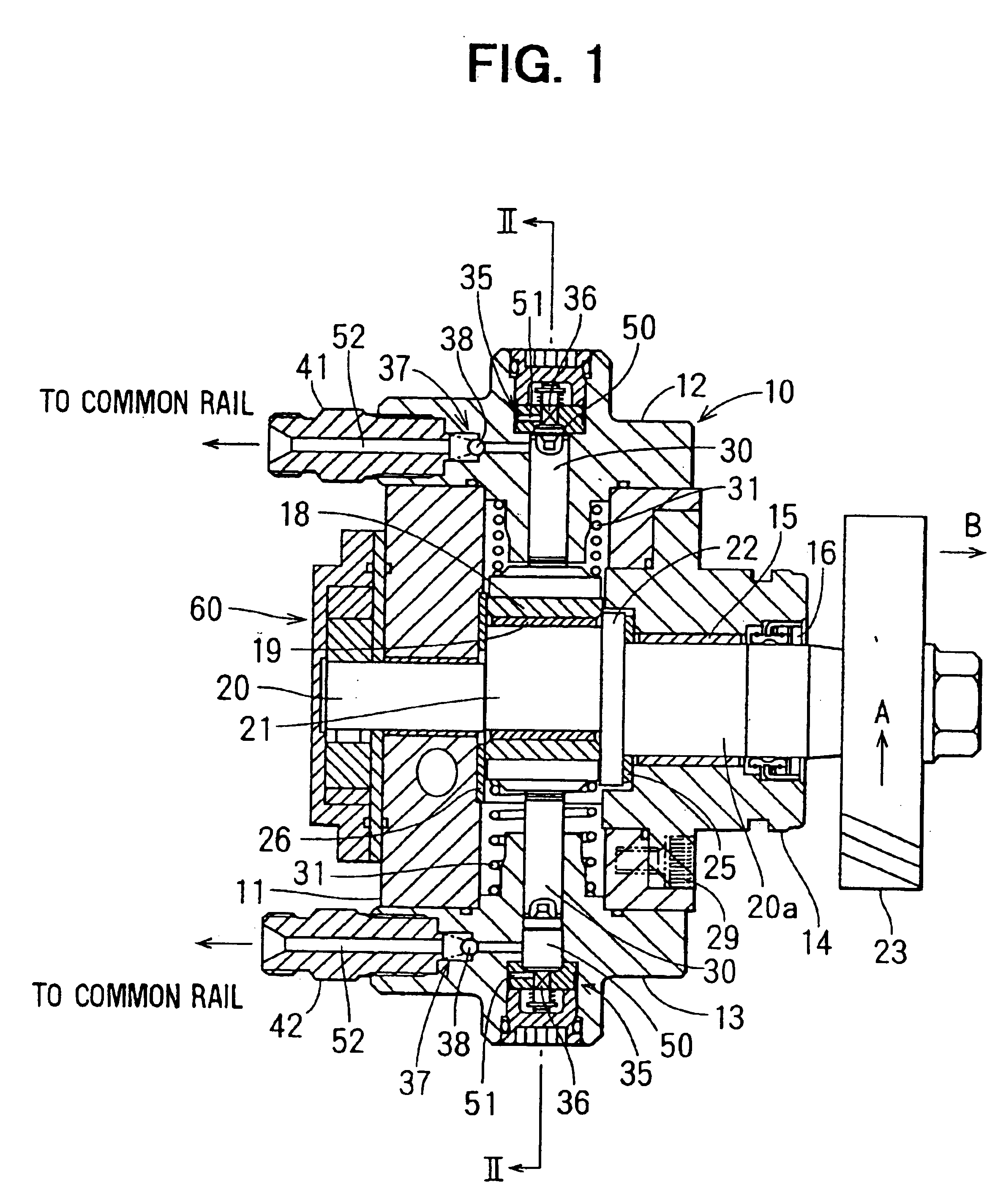
A fuel injection pump for a diesel engine according to a first embodiment of the present invention is described with reference to FIGS. 1 and 2.

As shown in FIG. 1, a pump housing of the fuel injection pump 10 is composed of an aluminum housing body 11 and a pair of iron cylinder heads 12 and 13. Each of the cylinder heads 12 and 13 has a bore in which a plunger 30 as a moving member is slidably and reciprocatingly held. A fuel pressure chamber 50 is formed in each of the bores of the cylinder heads 12 and 13 between an end of the plunger 30 and an end of a return valve 35 having a return valve element 36.

A bearing cover 14 is fixed to the housing body by bolts 29. A journal bearing 15 for holding a camshaft 20 is rigidly fitted into a center bore of the bearing cover 14.

The camshaft 20 is rotatably held by the housing body 11 and by the bearing cover 14 via the journal bearing 15. An oil seal 16 seals a clearance between the central bore of the bearing cover 14 and...

second embodiment

(Second Embodiment)

A fuel injection pump according to a second embodiment is described with reference to FIG. 3. Construction and feature same as those of the first embodiment have same reference numbers.

A bearing cover 80, which is a first connecting member, is fastened to the housing body 11 by bolts 29. A screw 81, which is a second connecting member, is screwed into the bearing cover 80. The screw 81 is provided inside with a journal bearing 82 by which the camshaft is rotatably held. A disk shaped member 71, which is formed integrally with the camshaft 70, is located at a portion of the camshaft 70 extending forward away from the cam 21 to a direction in which the camshaft 70 receives a driving force through the helical gear 23. The disk shaped member 71 is housed in a space 100 of the bearing cover 80 that is provided between the bearing cover 80 and the screw 81. The disk shaped member 71 is put between washers 83 and 84 in the space 100 of the bearing cover 80. The washer 83...


PUM


Abstract

In a fuel injection pump, a helical gear is attached to an end of a camshaft and rotatable with the camshaft. The camshaft is biased in one axial direction thereof by a driving force that the helical gear receives from an engine crankshaft. A disk is provided in a position of the camshaft extending forward from a cam to the direction in which the camshaft is biased. An axial movement of the disk is restricted via a washer by an end of a bearing cover. The disk is formed in the same axis to a portion of the camshaft that is held by a journal bearing. An outer diameter of the disk is larger than that of the cam. An area where the disk and the washer are in sliding contact with each other is relatively large and the sliding regions thereof are constant so that hammer noises are prevented and frictional wear thereof are limited.

Description

CROSS REFERENCE TO RELATED APPLICATIONThis application is based upon and claims the benefit of priority of Japanese Patent Application No. 2000-40959 filed on Feb. 18, 2000, the content of which is incorporated herein by reference.BACKGROUND OF THE INVENTION1. Field of the InventionThe present invention relates to a fuel injection pump for an internal combustion engine (hereinafter called engine), in particular, a construction of the pump with no hammer noises and less frictional wear.2. Description of Related ArtIn a conventional fuel injection pump, a driving force is transmitted to a camshaft via a belt or a gear from an engine crankshaft. A cam attached to the camshaft drives a movable member so that the movable member makes a reciprocating movement. Accordingly, the fuel injection pump pressurizes and delivers fuel sucked in a fuel pressure chamber.When the camshaft is rotating, the camshaft often moves in an axial direction thereof so that the cam is likely to hit a surface of...

Claims


Application Information

Patent Timeline
Patent Type & Authority Patents(United States)
IPC IPC(8): F02M63/02F02M59/10F02M59/00F02M59/06F02M63/00F04B53/00F02M39/00F04B1/04F04B1/00F04B1/02F02M39/02F02M59/02F02M59/44
CPCF02M39/005F02M59/06F02M59/102F04B53/006F04B1/02F04B1/0404F02M63/0225
Inventor MORI, KATSUMI
Owner DENSO CORP
Why Eureka
Try Eureka