
Method and device for unifying imbricated flows

a technology of imbricated flows and methods, applied in the direction of conveyors, rotary presses, printing, etc., can solve the problems of no suitable devices, product compression or even crease, etc., and achieve the effect of increasing the capacity

Inactive Publication Date: 2010-02-04
FERAG AG
View PDF15 Cites 10 Cited by
  • Summary
  • Abstract
  • Description
  • Claims
  • Application Information

AI Technical Summary

Benefits of technology

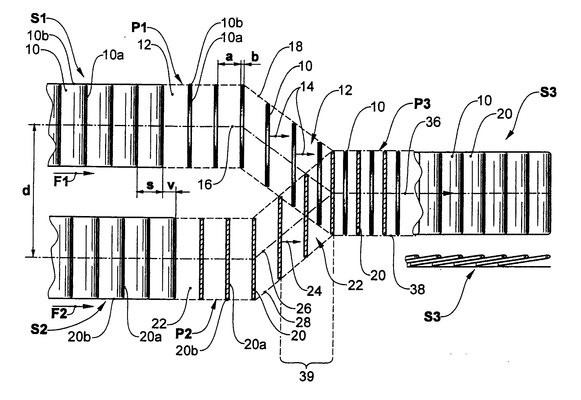
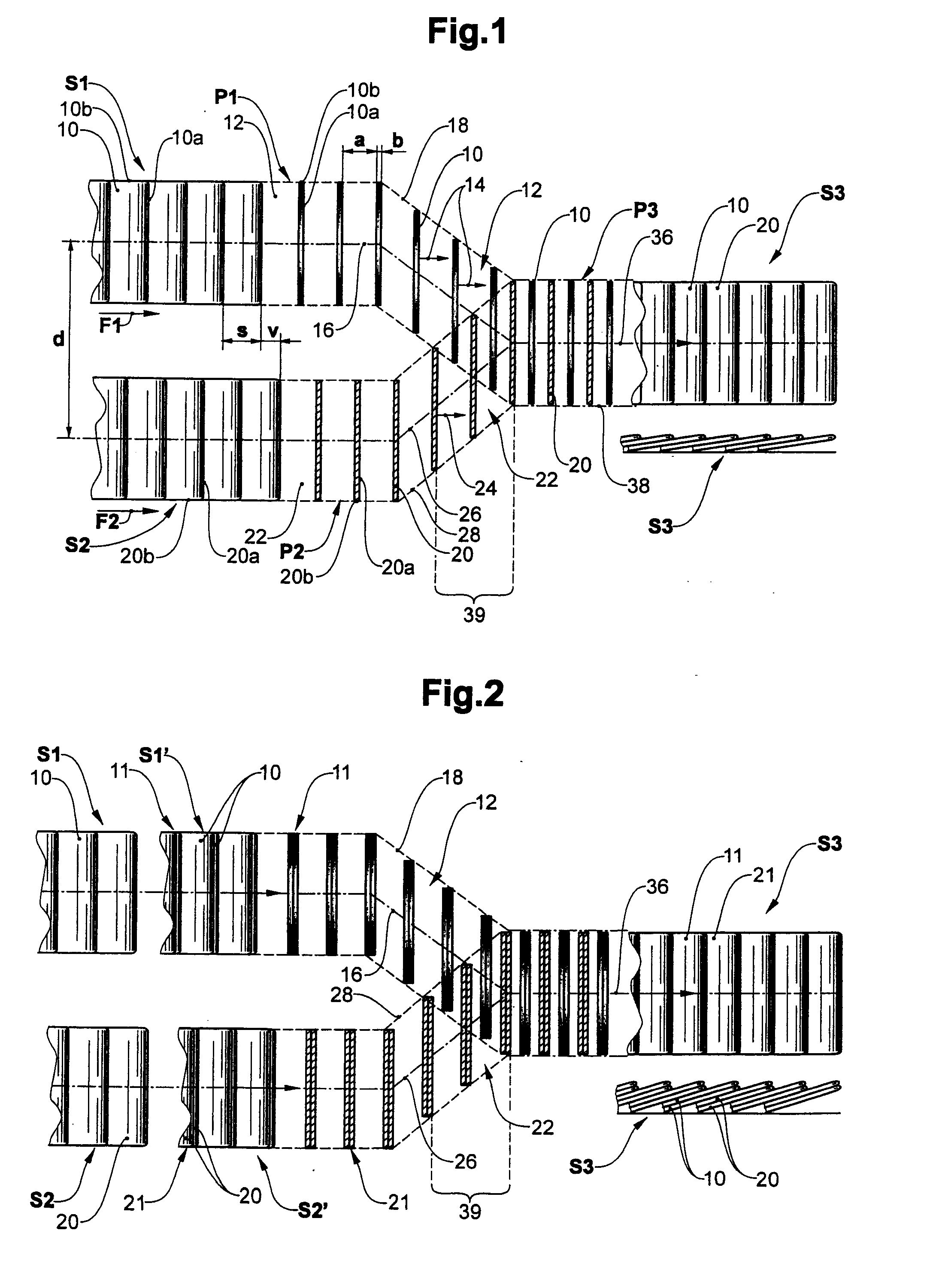
[0012]The method according to the invention assumes that flat products are conveyed in two imbricated flows which are spatially separated from one another, i.e. in a compact formation with a certain overlap of the products. Since the products normally lie in an imbricated formation, the surface normals as a rule are orientated essentially vertically, and thus, essentially perpendicularly to the conveyor direction. The flows are received by an intermediate conveyor and are conveyed further as a first or second product flow. Thereby, space intervals are created between individual products or at least between groups of products, which are conveyed directly overlapping one another in the initial formation. Space interval is to be understood in that in each case two products are distanced to one another, so that at least one front surface or rear surface of a product is preferably essentially completely exposed. In each case, one or more products of the respective other product flow may be introduced in a gentle manner into these space intervals without rubbing on one another. In order to avoid a space-consuming and mechanically burdening pulling-apart of the products in the plane of the products, the orientation of the products, at least of one of the product flows, is changed such that its surface normals point essentially in the horizontal direction directly before the unification of the product flows. This orientation change may be effected without a great effort by way of using gravitational force. A spatially compact formation with space intervals arises without having to significantly accelerate the products in the conveyor direction. The products of at least one of the product flows are then inserted with an essentially horizontal orientation of their surface normals or in a hanging or standing position, into the space intervals within the other product flow.
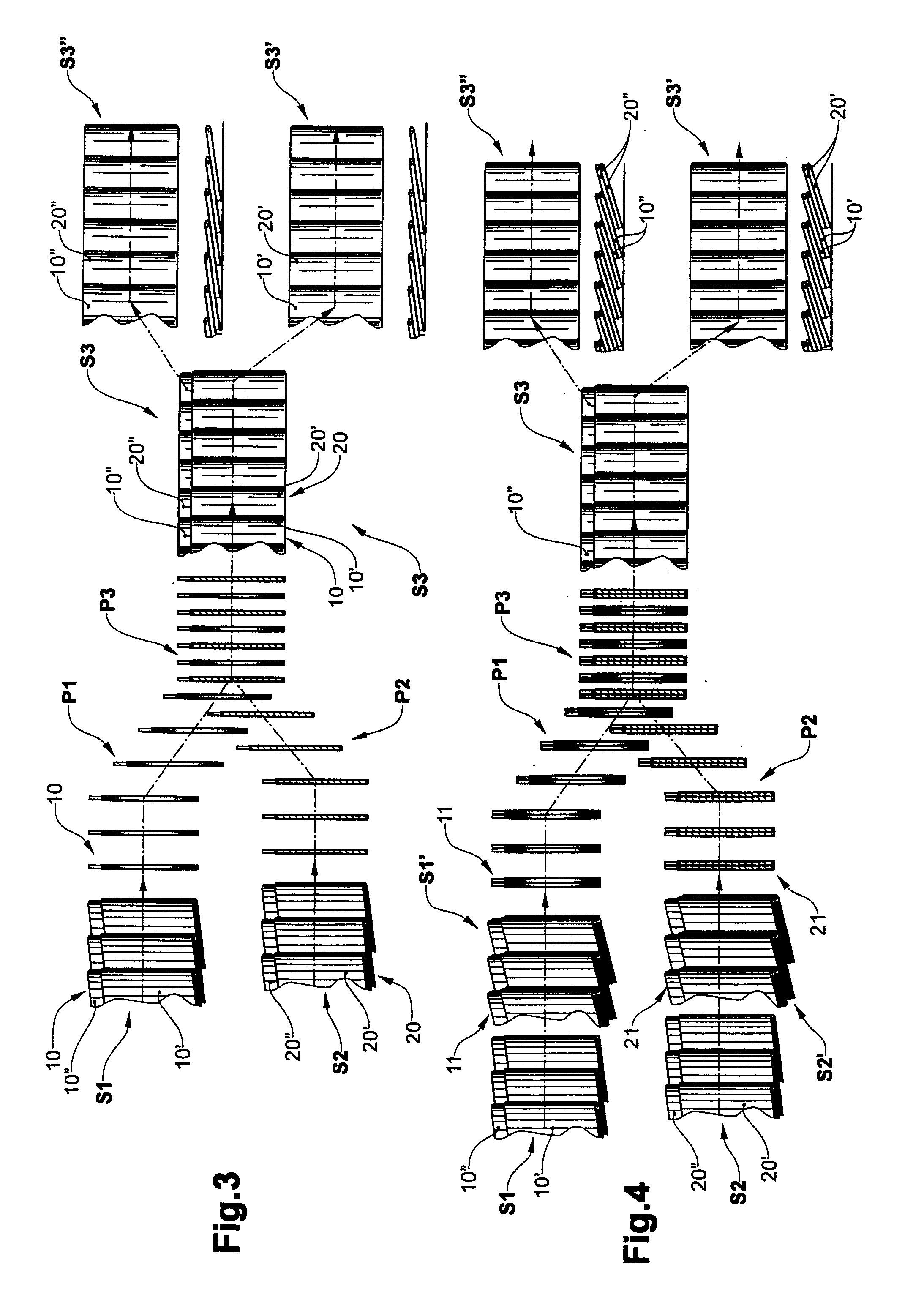
[0018]As an alternative, the space intervals may be produced by way of the products being introduced into conveyor compartments of a rotatable conveyor drum individually or preferably in groups. They are introduced from above, preferably on account of gravity, with a horizontal alignment of their surface normals. After depositing in the conveyor compartment, the surface normal of the products points in the direction of the surface normal of the support surface of the conveyor compartments, whose direction preferably corresponds to the conveyor direction. A conveyor compartment in each case receives products from the first and second imbricated flow. These are fed at different axial positions and are pushed onto one another in the axial direction by way of an additional pusher means or by way of gravity. If the axial displacement of the products from the first product flow is effected before the feeding of the products from the second product flow, then a particularly gentle treatment of the products is effected, since one avoids the products rubbing over one another.
[0020]The inventive device for carrying out the method includes conveyor means which are capable of receiving the products from the first and the second imbricated flow and conveying them into a first product flow or into a second product flow. Such conveyor means are for example grippers, pockets or also conveyor compartments of a conveyor drum. The products are conveyed such that the space intervals described above are created at least for a short time. Furthermore, means for displacing the products of the first product flow are present, which move these relative to one another in a plane running essentially perpendicularly to the surface normals, into the space intervals within the second product flow. By way of this, the distance of the product flows is also reduced and finally a common product flow consisting of products from the first and the second imbricated flow are formed. These means may, for example, be realised by way of conveyer paths of the grippers or pockets, which approach one another. With a conveyor compartment which receives products from the first or second imbricated flow at different axial positions, these means may be realised by way of a pusher acting in the axial direction. Alternatively or additionally, the gravitational force may also be utilised, e.g. by way of the products sliding from above into pockets, grippers or conveyor compartments, in which products are already located.
[0022]The invention permits a gentle, space-saving unification of two product flows, and, given an equal conveying of several products, permits the achievement of a significant increase in the capacity. For this, to some degree conveyor devices known per se are applied in a new manner. For this reason, the invention may be realised without any great design effort.

Problems solved by technology

Since the running-in imbricated formations are not broken up, here it may occur that the products are compressed or even creased due to the friction, particularly if these are thin or still moist from the printing.
With the conveyor outputs and conveyor speeds which are usual today, at present there are no suitable devices, e.g. gripper conveyors with a corresponding conveyor capacity.

Method used


Image

  • Method and device for unifying imbricated flows
  • Method and device for unifying imbricated flows
  • Method and device for unifying imbricated flows

Examples


Embodiment Construction

[0033]FIG. 1 shows a principle sketch of the method according to the invention, for unifying two imbricated flows S1, S2 into a common product flow P3. Represented is a plan view of the imbricated flows or product flows. The imbricated flows S1, S2 consist in each case of products 10, 20 which are arranged in a lying manner and overlapping one another with an imbricated distance s. The products 10, 20 may be identical or different. Here, it is the case of folded products 10, 20, e.g. newspapers or magazines.

[0034]The imbricated flows S1, S2 are firstly converted into product flows P1, P2 of singularised products 10, 20. For this, the products 10, 20 for example, are received individually by way of grippers of an intermediate conveyor (cf. FIG. 5-8) The products 10, 20 are brought into a hanging position, and the surface normals 10, 24 point in the horizontal direction and the leading edges or side edges 10a, 20a, and 10b, 20b respectively in the horizontal or vertical direction. The...


PUM

PropertyMeasurementUnit
Distanceaaaaaaaaaa
Displacementaaaaaaaaaa

Abstract

A method and a device are provided for combining overlapping flows (S1, S2) of flat products (10, 20), particularly of printed products, to common product flows (P3). The products (10, 20) from the first or second overlapping flows (S1, S2) are received by an intermediate conveyor (50), and transported to a first product flow (P1), or a second product flow (P2), by means of the intermediate conveyor (50). The distance (d) of the product flows (P1, P2) is successively reduced so that the product flows (P1, P2) form the common product flow (P3). The products (10, 20) are conveyed at least directly before combining the product flows (P1, P2) such that a space (12, 22) is located at least between the groups of products (10, 20) within the first, or within the second product flow (P1, P2). The products (10, 20) of at least one of the product flows (P1, P2) are displaced in a direction extending substantially perpendicular to the surface normal (14, 24) relative to the products (10, 20) of the other product flow (P1, P2).

Description

BACKGROUND OF THE INVENTION[0001]1. Field of the Invention[0002]The invention lies in the field of conveyor technology for flat products, in particular printed products, and relates to a method for unifying at least one first imbricated flow and a second imbricated flow distanced thereto, as well as to a device for carrying out the method.[0003]2. Description of Related Art[0004]It is particularly in the field of processing printed products that the task of leading together imbricated flows of flat products into a common product flow often occurs, wherein the original flows are separate from one another. The common product flow may either be an imbricated flow, but may also designed differently, e.g. a flow of products gripped individually or in groups by grippers, or one or more stacks of several products. For example, some rotation printing machines feed printed products in pairs folded into one another with a lateral offset, into an imbricated formation. Two separate imbricated f...

Claims


Application Information

Patent Timeline
IPC IPC(8): B65H39/06B65H29/66B65G37/00B65G47/30B41F21/00
CPCB65H29/6681B65H39/06B65H2301/44472B65H2301/44474B65H2301/44712B65H2301/44732B65H2220/01B65H2220/02
Inventor MULLER, ERWIN
Owner FERAG AG
Learn More