
High energy photon detection using pulse width modulation

a high-energy photon and pulse width technology, applied in the field of imaging, can solve problems such as the problem of deteriorating signal quality and the problem of analog signals being sent for processing

Active Publication Date: 2010-02-04
THE BOARD OF TRUSTEES OF THE LELAND STANFORD JUNIOR UNIV
View PDF8 Cites 49 Cited by
  • Summary
  • Abstract
  • Description
  • Claims
  • Application Information

AI Technical Summary

Benefits of technology

[0007]Embodiments of the invention provide, among other things, methods and systems for processing an analog signal that is generated by a high energy photon detector in response to a high energy photon interaction. In an example method, a digital edge is generated representing the time of the interaction along a first path, and the energy of the interaction is encoded as a delay from the digital edge along a second path. The generated digital edge and the delay encode the time and energy of the analog signal using pulse width modulation.

Problems solved by technology

However, the transmission of such analog signals for processing can present problems.
Additionally, the quality of the signal may deteriorate, particularly if the detector is located in certain environments (as a nonlimiting example, magnetic environments, such as within a magnetic resonance imaging (MRI) detector), or is multiplexed to reduce number of readout channels.

Method used


Image

  • High energy photon detection using pulse width modulation
  • High energy photon detection using pulse width modulation
  • High energy photon detection using pulse width modulation

Examples


Embodiment Construction

[0025]As described above, in standard high energy photon detectors, for an event such as a scintillation event, information from individual interactions is recorded, such as the time of the event, the energy of the event, and the location of the event. These parameters are determined through certain analog signal processing algorithms applied to the analog signals that the detector generates. For example, the energy and location information may be processed using an analog-to-digital (ADC) converter that samples an analog value that is proportional to the integral of the charge created by the scintillation event.

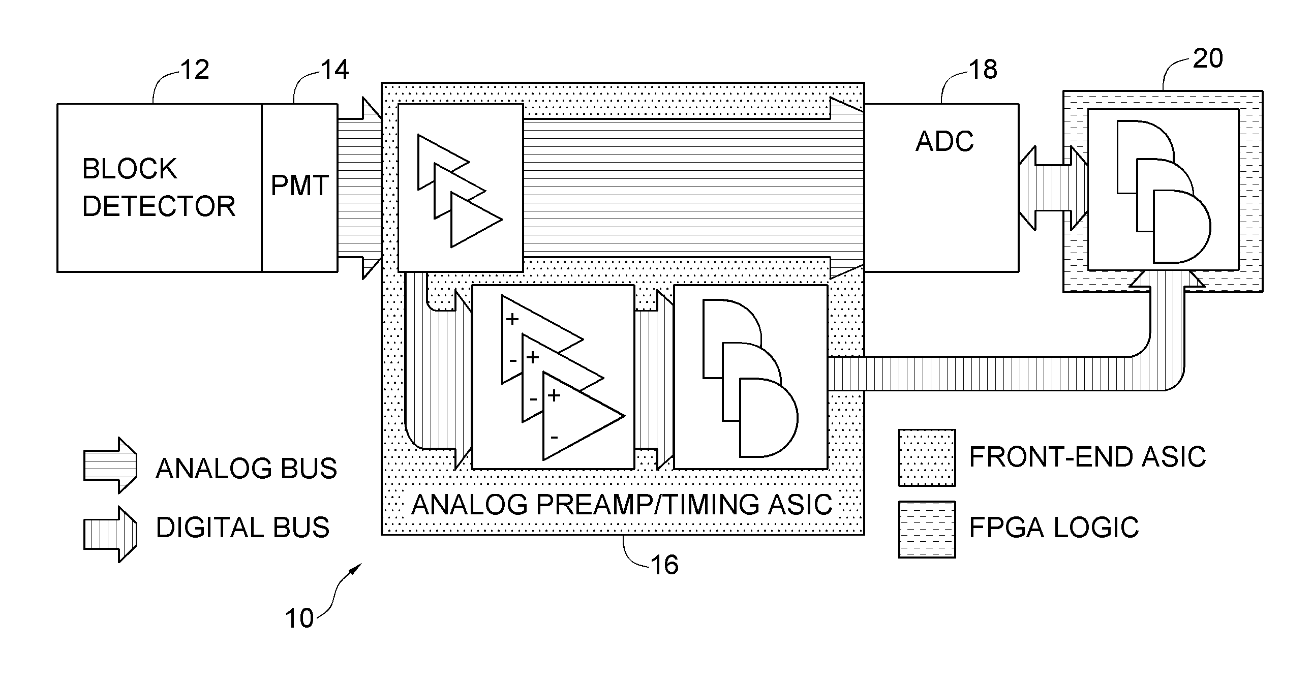
[0026]However, more recent, very high resolution high energy photon detection systems require new data acquisition architectures to accommodate the large increase in the number of readout channels. For example, FIG. 4 shows light multiplexing being used to reduce the number of readout channels in a conventional PET block detector readout system 10. In FIG. 4, a block detecto...


PUM


Abstract

Methods and systems for processing an analog signal that is generated by a high energy photon detector in response to a high energy photon interaction. A digital edge is generated representing the time of the interaction along a first path, and the energy of the interaction is encoded as a delay from the digital edge along a second path. The generated digital edge and the delay encode the time and energy of the analog signal using pulse width modulation.

Description

PRIORITY CLAIM AND REFERENCE TO RELATED APPLICATION[0001]This application claims the benefit of U.S. Provisional Application Ser. No. 61 / 067,905, filed Mar. 3, 2008, under 35 U.S.C. §119. U.S. Provisional Application Ser. No. 61 / 067,905 is incorporated in its entirety by reference herein.STATEMENT OF GOVERNMENT INTEREST[0002]This invention was made with Government support under contracts EB003283 and CA119056 awarded by the National Institutes of Health. The Government has certain rights in this invention.FIELD OF THE INVENTION[0003]A field of the invention is imaging. Example applications of the invention include, but are not limited to, nuclear imaging, nuclear medicine, defense applications, and oil well drilling.BACKGROUND OF THE INVENTION[0004]High energy photons need to be detected in a variety of applications including but not limited to nuclear science, high energy physics, astronomy, and medical imaging. In many high energy photon (e.g., x-ray, gamma ray or annihilation pho...

Claims


Application Information

Patent Timeline
Patent Type & Authority Applications(United States)
IPC IPC(8): G01T1/164G01J1/44
CPCG01T1/1647
Inventor OLCOTT, PETER D.LEVIN, CRAIG S.
Owner THE BOARD OF TRUSTEES OF THE LELAND STANFORD JUNIOR UNIV
Learn More