
Intra-area master reactive controller for tightly coupled windfarms

a reactive controller and tightly coupled technology, applied in the direction of electric generator control, mechanical equipment, machines/engines, etc., can solve the problems of reducing regulating requirements, common coupling, and the inability to control the plurality of local windfarm controllers

Active Publication Date: 2010-02-04
GENERAL ELECTRIC CO
View PDF11 Cites 162 Cited by
  • Summary
  • Abstract
  • Description
  • Claims
  • Application Information

AI Technical Summary

Benefits of technology

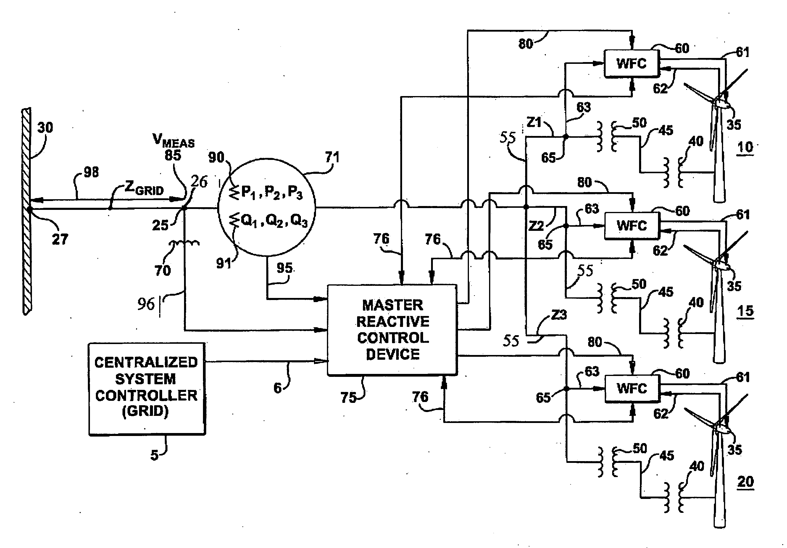
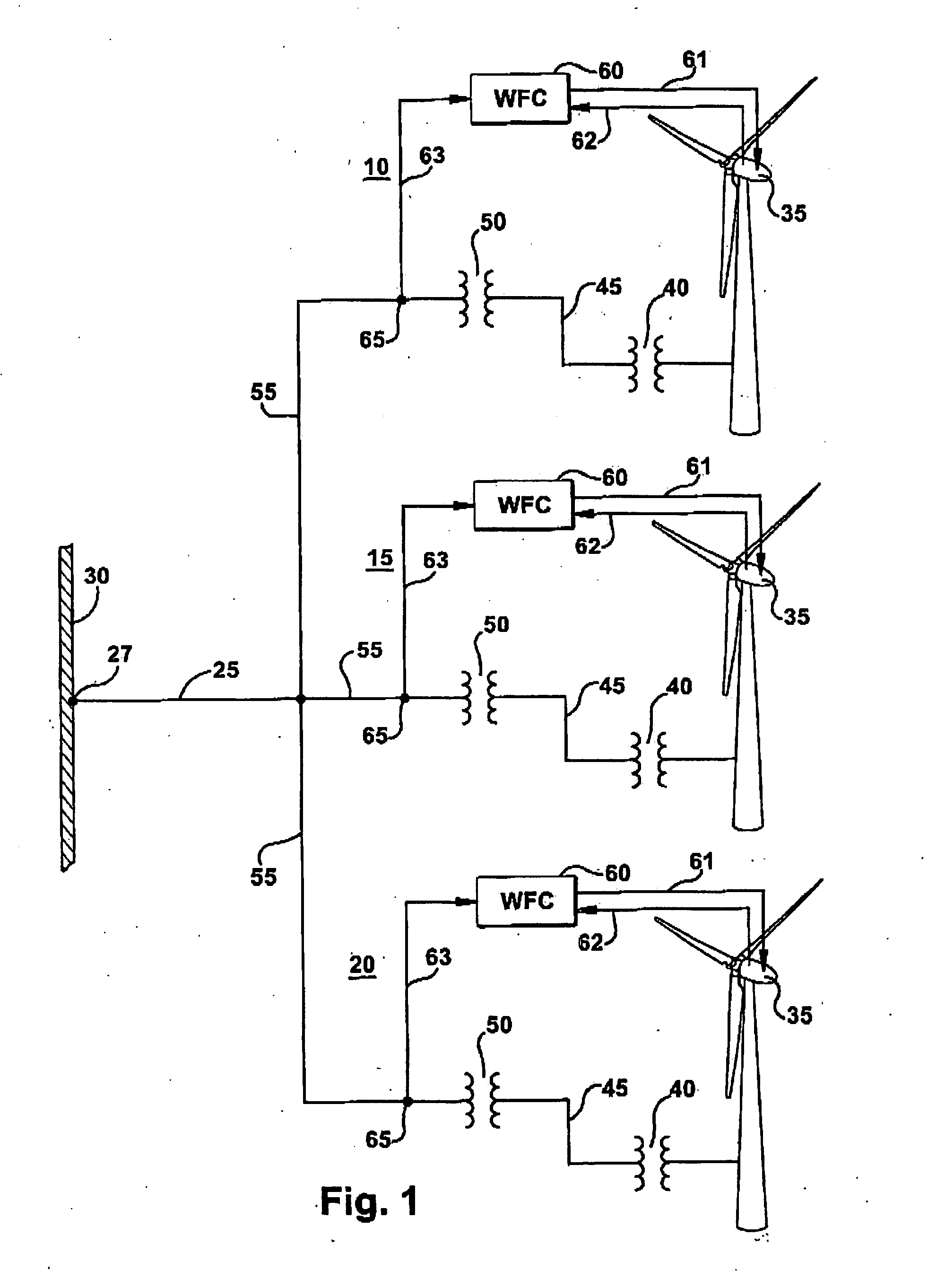
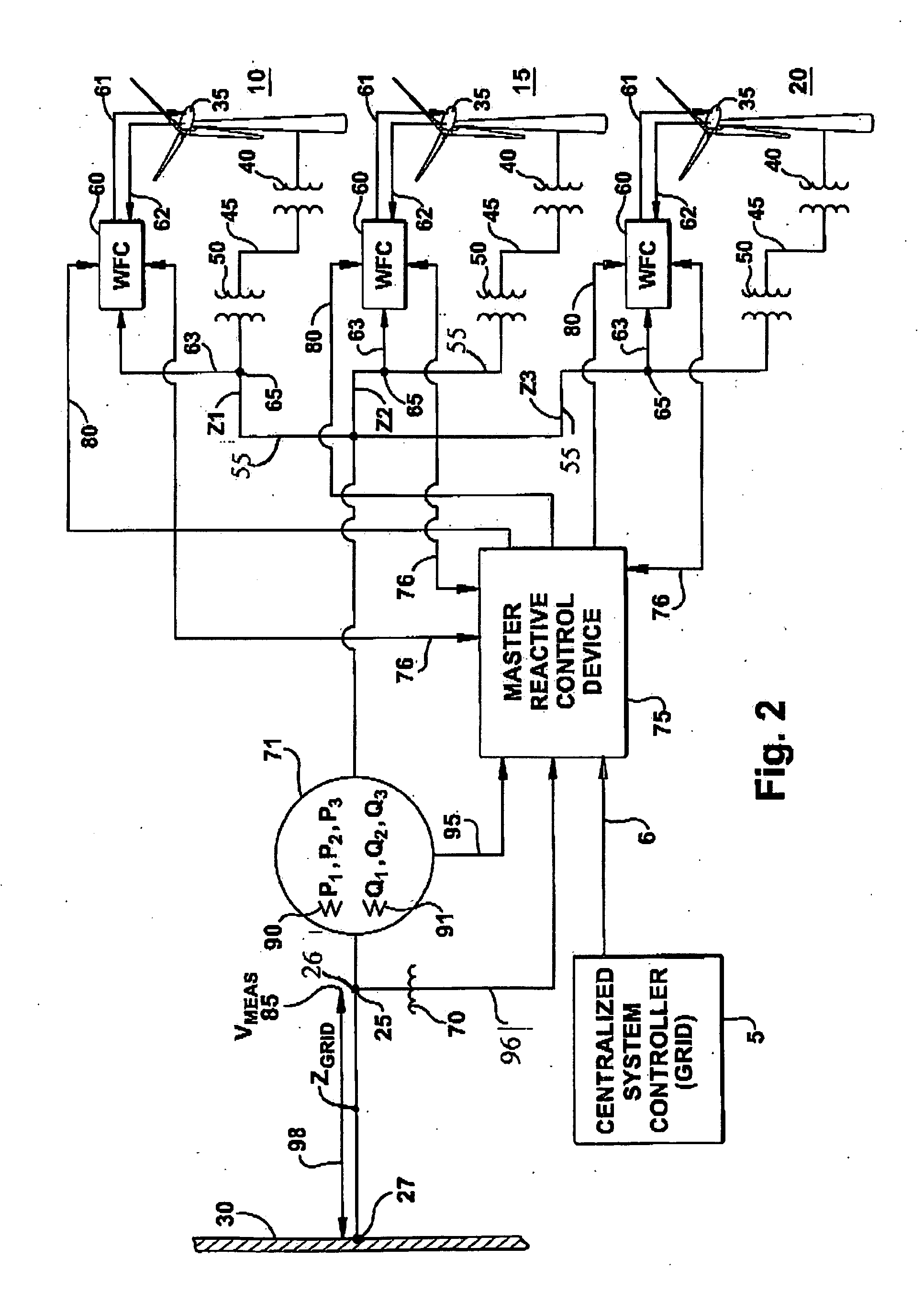
[0011]According to a first aspect of the present invention, a wind turbine generator control system is adapted for controlling output of a plurality of tightly-coupled local windfarms connected at a point of common connection and tied to a power grid wherein each local windfarm includes a plurality of wind turbine generators. The wind turbine generator control system may include a local windfarm controller for each of the plurality of local windfarms, wherein the local windfarm controller controls operation of the plurality of wind turbine generators within the local windfarm, including control for the generation of real power and reactive power for an individual generator of the plurality of wind turbine generators within the voltage and thermal limits of the individual wind turbine generator. A receiving means accepts power-related reference signals from a centralized system controller for the electric power grid and power-related parameters for the operation of the individual local windfarms. A sensing means determines a plurality of power-related parameters at a point of common coupling for the plurality of tightly-coupled windfarms.
[0012]A master reactive control device (also known as a master intra-area controller) employs power-related reference signals from the central system controller for the grid, the plurality of sensed power-related parameters from the local controller, and the power-related parameters sensed at the point of common coupling to generate a plurality of power-related commands to each local windfarm controller for the plurality of tightly-coupled local windfarms to command a common power-related parameter at the point common coupling.

Problems solved by technology

However, the plurality of individual local windfarm controllers cannot control at the point of common coupling 25 because the power-related parameters at that point are a combination of the outputs from all of the individual windfarms.
Typically such problems have been side stepped by reducing regulating requirements, or constraining operation.
This approach may often reduce the regulation quality and may not ultimately meet the requirements for the power system interconnect standards.
This solution is a more expensive approach, requiring extra measurement instrumentation and control complexity, such that the complexity makes it difficult to apply.

Method used


Image

  • Intra-area master reactive controller for tightly coupled windfarms
  • Intra-area master reactive controller for tightly coupled windfarms
  • Intra-area master reactive controller for tightly coupled windfarms

Examples


Embodiment Construction

[0023]The following embodiments of the present invention have many advantages including regulating the output of tightly-coupled windfarms, connected to a grid of an electrical power system, so as to jointly regulate a single common point of electrical coupling through coordinated real power, reactive power and voltage response. A master reactive control device (MRCD) may monitor a common measurement point for power-related parameters (such as currents, voltage, real power, reactive power and power factor) where the parameter value at the measurement point is an aggregate sum of the contributions for each local windfarm. Line drop compensation may be applied, if necessary, to compensate for real power losses, reactive power losses, and voltage drops that may be required if the measurement point is not at the point in the system at which the combined output of the windfarms is to be regulated. The master reactive control device may incorporate a reactive power output command that can...


PUM


Abstract

A wind turbine generator control system is provided for controlling output of a plurality of tightly-coupled windfarms connected at a point of common coupling with a power system grid. A master reactive control device employs algorithms whose technical effect is to coordinate the real power, reactive power and voltage output of the multiple windfarms. The controller incorporates a reactive power regulator that can be used to regulate reactive power, power factor or voltage at the point of common coupling and an active power regulator that can be used to regulate real power at the point of common coupling; such that each windfarm is not asked to contribute or violate its own operating capability.

Description

BACKGROUND OF THE INVENTION[0001]The invention relates generally to control of multiple electrical windfarm systems within an electric power system and more specifically to a master controller and method for controlling a plurality of interconnected windfarms at a point of common coupling with the electric power system.[0002]Typically, an electric power system includes a plurality of power generation assets, which are spread over a geographic area. The electric power system also includes systems that consume power (loads) that may also be spread over the geographic area. The electric power system also includes a grid, a network of electric power lines and associated equipment used to transmit and distribute electricity over a geographic area. The infrastructure of the grid, may include, but is not limited to devices for interconnection, control, maintenance, and improvement of the electric power system operation. Typically, the electric power system includes a centralized control sy...

Claims


Application Information

Patent Timeline
Patent Type & Authority Applications(United States)
IPC IPC(8): F03D7/00
CPCF03D7/0284F03D7/047F03D7/048Y02E10/563Y02E10/763H02J3/383H02J3/386Y02E10/723Y02P80/14H02M1/00H02J2300/28H02J2300/24H02J3/381Y02E10/56Y02E10/76Y02E10/72H02M1/0016H02J3/50
Inventor CARDINAL, MARK E.MILLER, NICHOLAS W.CLARK, KARA
Owner GENERAL ELECTRIC CO
Learn More