Method for estimating formation skin damage from nuclear magnetic resonance measurements

Inactive Publication Date: 2010-02-04
SCHLUMBERGER TECH CORP
View PDF3 Cites 11 Cited by
  • Summary
  • Abstract
  • Description
  • Claims
  • Application Information

AI Technical Summary

Problems solved by technology

Such near-wellbore permeability reduction is referred to as “skin effect” or “skin damage” and may result in lower oil and/or gas flow rates than would be expected for the particular rock formation and/or higher pressure drop from the formation to the wellbore.
For certain

Method used


Image

  • Method for estimating formation skin damage from nuclear magnetic resonance measurements
  • Method for estimating formation skin damage from nuclear magnetic resonance measurements
  • Method for estimating formation skin damage from nuclear magnetic resonance measurements

Examples


Embodiment Construction

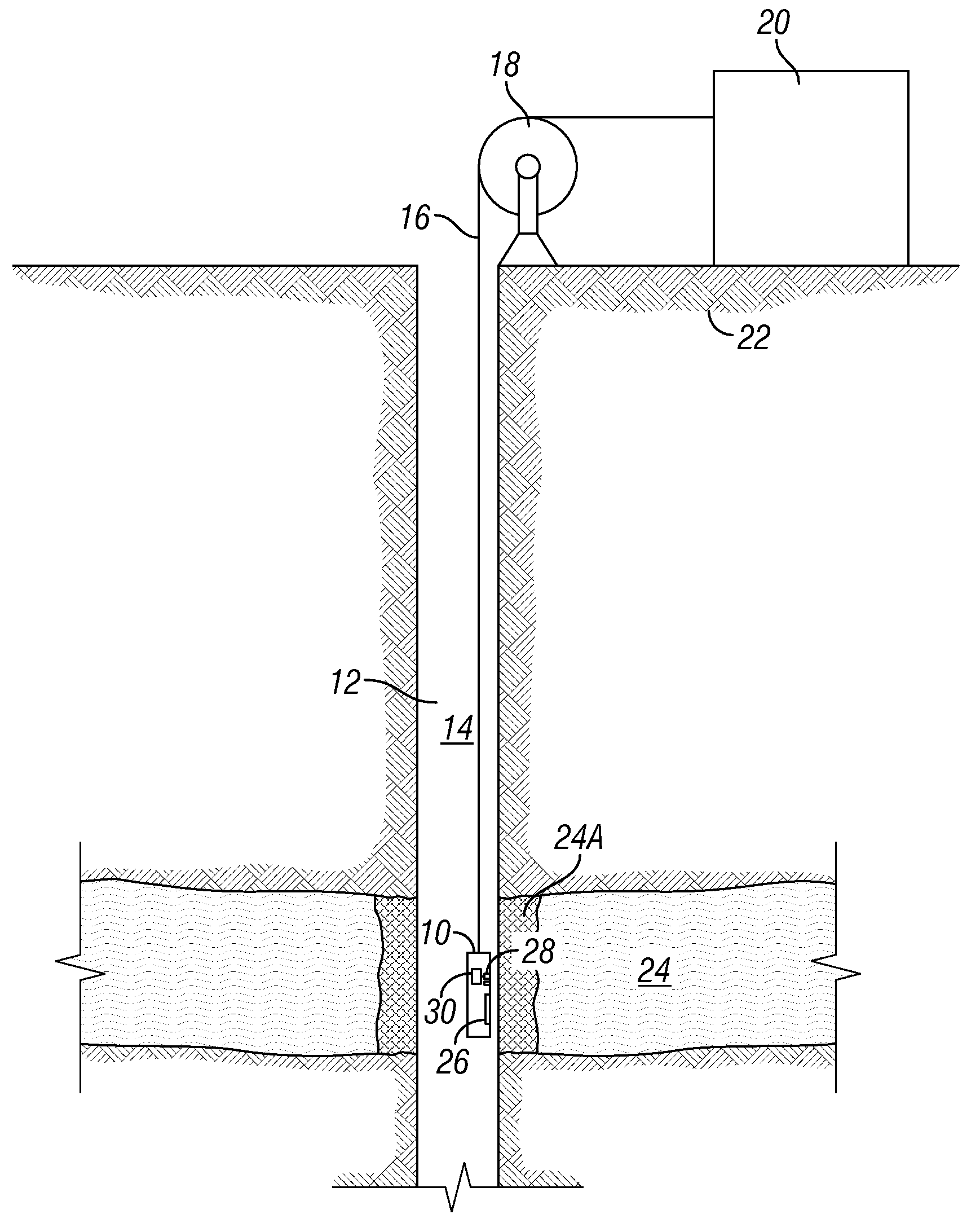
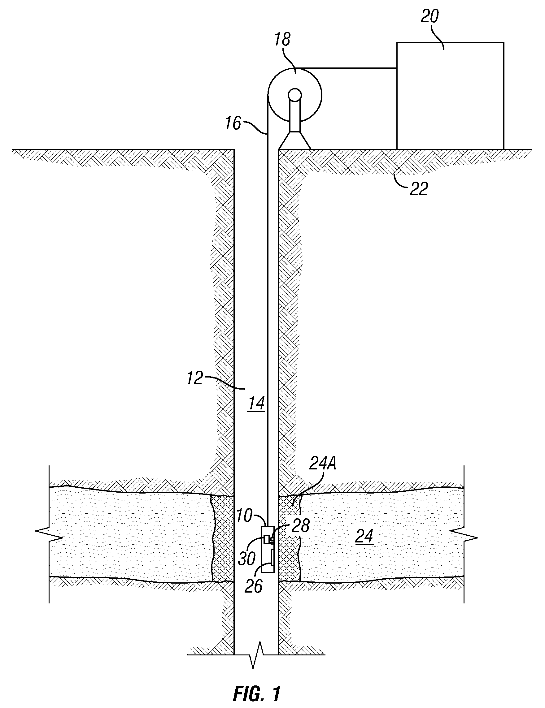
[0014]FIG. 1 shows an example of a nuclear magnetic resonance (“NMR”) well logging instrument 10 being moved along a wellbore 12 drilled through subsurface rock formations 22, including one or more permeable rock formations 24. The instrument 10 may be moved along the interior of the wellbore 12 at the end of an armored electrical cable 16 (“wireline”) deployed by a winch 18 or similar device known in the art. The instrument 10 may be in signal communication with a surface deployed “recording unit”20 that may include systems (not shown separately for clarity of the illustration) for providing electrical power to operate the instrument 10, to receive and decode signals from the instrument 10 and to make a recording, indexed with respect to depth of the instrument in the wellbore or indexed with respect to time, of the signals transmitted from the instrument 10 to the recording unit 20.

[0015]While wireline deployment is shown in FIG. 1, it is to be clearly understood that such deploym...


PUM


Abstract

A method for determining skin factor of a subsurface rock formation from within a wellbore drilled therethrough includes measuring a nuclear magnetic resonance property of the formation at a plurality of lateral depths therein. The measured nuclear magnetic resonance property is used to estimate the skin factor.

Description

CROSS-REFERENCE TO RELATED APPLICATIONS [0001]Priority is claimed from U.S. Provisional Application No. 61 / 084,309 filed on Jul. 29, 2008.STATEMENT REGARDING FEDERALLY SPONSORED RESEARCH OR DEVELOPMENT [0002]Not applicable.BACKGROUND OF THE INVENTION [0003]1. Field of the Invention[0004]The invention relates generally to the field of subsurface rock formation productivity estimation. More specifically, the invention relates to methods for determining “skin” damage of a formation proximate a wellbore so that expected fluid production can be predicted.[0005]2. Background Art[0006]Wellbores are drilled through subsurface rock formations to extract useful substances such as oil and gas. A wellbore forms a hydraulic conduit from a permeable subsurface rock formation having oil and / or gas present therein to the Earth's surface. Oil and / or gas typically move to the surface through the wellbore by the force of gravity. Gravity manifests itself as a pressure drop between the fluid pressure i...

Claims


Application Information

Patent Timeline
IPC IPC(8): G01V3/32
CPCG01V3/32
Inventor MINH, CHANH CAO
Owner SCHLUMBERGER TECH CORP
Why Eureka
Try Eureka