Camera-based tracking and position determination for sporting events

a technology of position determination and camera-based tracking, applied in the field of camera-based tracking and position determination for sporting events, can solve the problems of difficult or in some cases impossible to determine the location of a ball during play, and the delay in this process can be relatively long, so as to improve player and ball position tracking, improve the effect of accurate rule enforcement and optimal coverag

Active Publication Date: 2010-02-04
CURRY GERALD
View PDF42 Cites 516 Cited by
  • Summary
  • Abstract
  • Description
  • Claims
  • Application Information

AI Technical Summary

Benefits of technology

[0010]Camera selection and viewpoint are selected in accordance with position information for balls, game equipment, and players during a game or sporting event. Such position information may be obtained, for example, using devices such as a transceiver, a transponder, an accelerometer, and / or a RADAR positioning device installed within a game ball, gaming equipment, apparel worn by players, and the like. Such devices can be fit or clipped onto, or embedded within, game equipment, apparel and clothing, and the like. In addition, infrared video-based tracking systems may be used in conjunction with the aforementioned positioning methods for better player and ball position tracking. Other positioning methods include digital signal processing (DSP) image processing techniques, LIDAR, and SONAR positioning techniques. Image processing techniques such as triangulation can be used to help detect the location of different objects. The position as well as other related data of the ball and / or associated players in a game can be determined in real-time. The data is used to select cameras and viewpoints for maximum interest, and is made available to officials for more accurate rules enforcement. Additionally, one embodiment (viewing mode) uses a 3D model of the gaming or event arena to position cameras (stationary and Pan-Tilt-Zoom) for optimal coverage. The position information from the players and ball is then used to determine the 3D location from where the game should be viewed. The multiple video signals (or video feeds) and interpolation techniques are used to construct the 2D viewer perspective from the 3D location determined.

Problems solved by technology

It is, however, often difficult to determine the location of a ball during play.
Often, the action in a game or sporting event occurs so quickly that it is difficult or in some cases impossible given the limits of human reaction speed for human observation and decision making to keep up with optimal selection of cameras and vantage point.
The delay in this process can be relatively long, as it depends on a multitude of human interactions.
In addition, EWSs (Extremely Wide Shot) or VWSs (Very Wide Shot) with “birds-eye view” camera angles are used more often than not in coverage, though such shots are lacking in detail and interest.
This is due to the unpredictable nature of the event and the need for a live feed, in combination with the reality that a closer shot may very well forgo the desired action.
The officiating task can be very difficult to perform accurately and requires special training.

Method used


Image

  • Camera-based tracking and position determination for sporting events
  • Camera-based tracking and position determination for sporting events
  • Camera-based tracking and position determination for sporting events

Examples


first embodiment

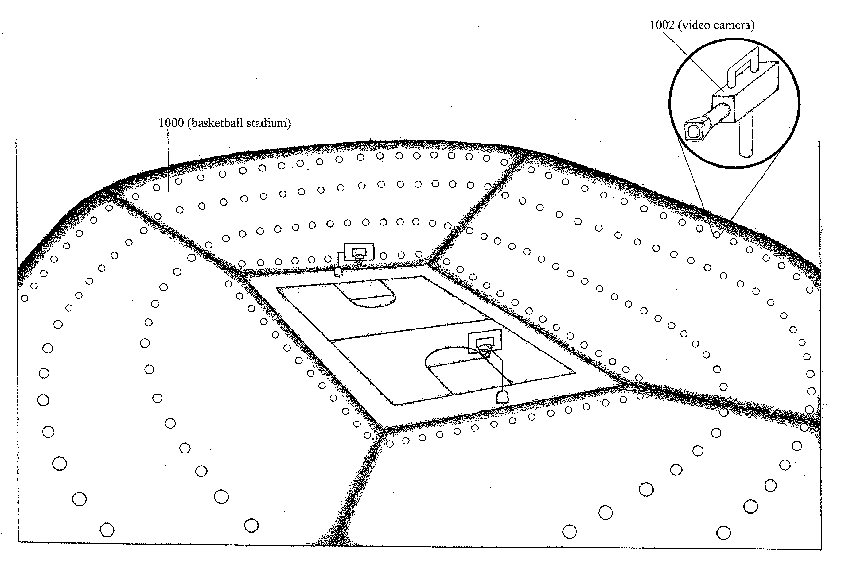
[0102]The system can have a variable range of integration with electronics and therefore can have varying degrees of complexity. For example, the simplest implementation or first embodiment, does not use software or player position information. The system also places various stationary and / or robotically controlled pan-tilt-zoom cameras around the event. The system then uses specialized hardware or FPGAs to implement a simple state machine to generate control signals and switch or multiplex the camera feed (from one camera to another) as the ball moves around the game of play. The different cameras are positioned to view the event from different locations around the event, and thus have different respective fields of view coverage, also referred to as field of view. The camera feed is the camera output (or video signal). The camera output may be video only, or the output may include video signal(s) or information, audio signal(s) or information, other data, or some combination of al...

second embodiment

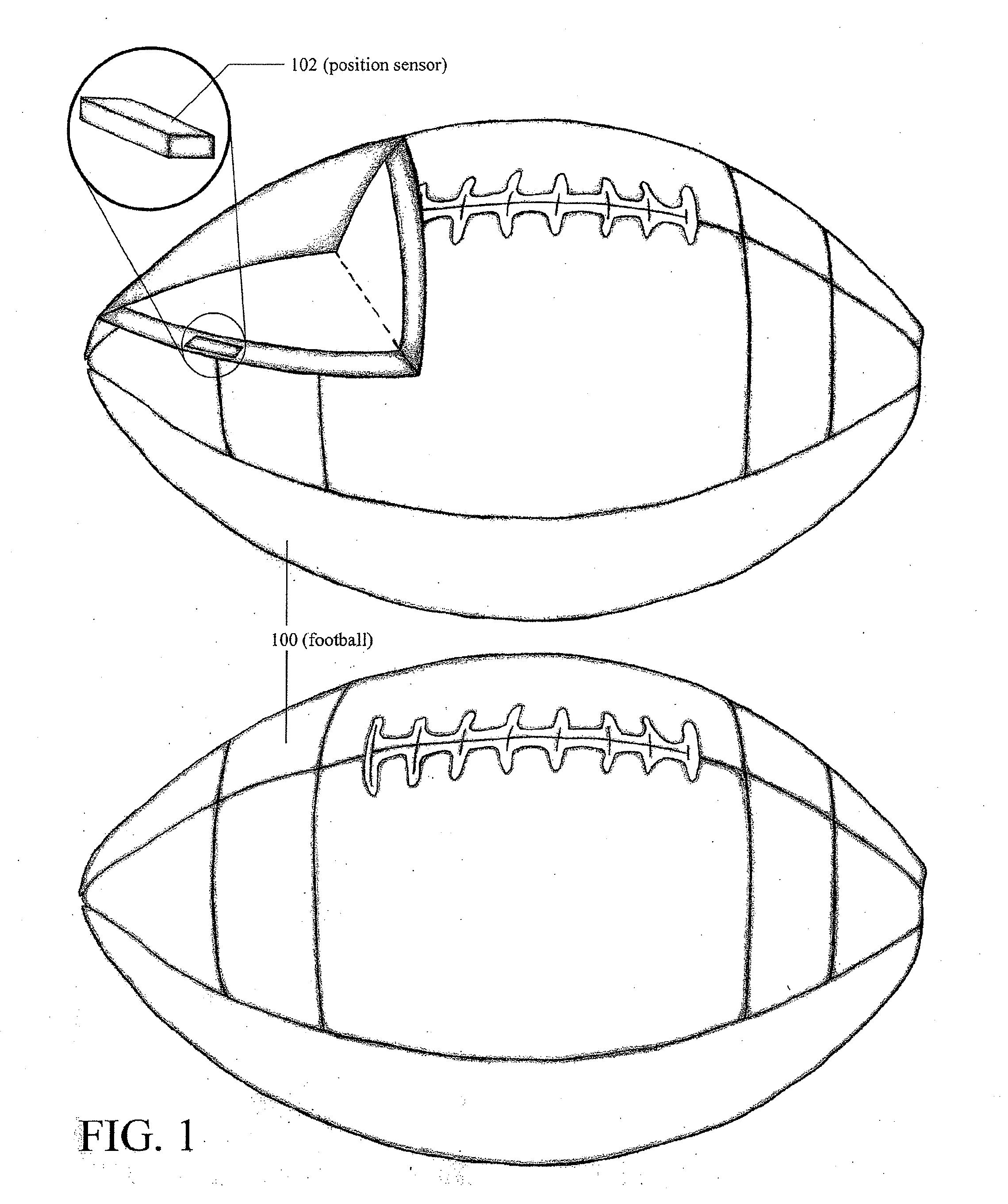
[0104]The second implementation or second embodiment of the system (without software) determines the position information of the ball and the players in a game of play and uses those inputs to compute how to access the camera selection / switching, shot type, and camera angle decision. This implementation works in much the same fashion as the first implementation, but now has more inputs, player and ball position information, from which to generate control signals. The control signals then tell the system which cameras to use (camera selection) and how to direct the robotically controlled pan-tilt-zoom cameras by changing the pan, tilt, zoom and focus functions. The system is able to multiplex or select one of the different camera outputs appropriately.

third embodiment

[0105]The third implementation or third embodiment uses a CPU and software. This third implementation only uses the ball position information to select the appropriate camera output and video signal. The fourth implementation uses the ball and player position information. In the third and fourth implementations, the CPU and software give the designer more flexibility in changing how the system should operate as the software can be changed more easily than custom hardware or FPGAs. Likewise, the fourth implementation uses the ball and player position information inputs to select the camera output or video signal. The third and fourth implementations decide based on the input position information how to change the camera switching / selection, shot type, and camera angle based on the software package. The stationary and robotically controlled pan-tilt-zoom cameras provide camera outputs and video signals that the system selects from based on the input position information data.

[0106]The...


PUM


Abstract

Position information of equipment at an event, such as a ball, one or more players, or other items in a game or sporting event, is used in selecting camera, camera shot type, camera angle, audio signals, and/or other output data for providing a multimedia presentation of the event to a viewer. The position information is used to determine the desired viewer perspective. A network of feedback robotically controlled Pan-Tilt-Zoom (PTZ), manually controlled cameras and stationary cameras work together with interpolation techniques to create a 2D video signal. The position information may also be used to access gaming rules and assist officiating of the event. The position information may be obtained through a transceiver(s), accelerometer(s), transponder(s), and/or RADAR detectable element(s) fitted into the ball, apparel or equipment of players, the players themselves, or other playing equipment associated with the game or sporting event. Other positioning methods that can be used include infrared video-based tracking systems, SONAR positioning system(s), LIDAR positioning systems, and digital signal processing (DSP) image processing techniques such as triangulation.

Description

CROSS-REFERENCE TO RELATED APPLICATIONS[0001]This application claims priority of co-pending U.S. Provisional Patent Application Ser. No. 61 / 137,261 entitled “Camera-Based Tracking And Position Determination For Sporting Events” by G. Curry filed Jul. 29, 2008 and U.S. Provisional Patent Application Ser. No. 61 / 209,377 entitled “Camera-Based Tracking And Position Determination For Sporting Events” by G. Curry filed Mar. 6, 2009. Priority of the filing dates of these Provisional Patent applications is hereby claimed, and the disclosures of these applications is hereby incorporated by reference.BACKGROUND[0002]1. Field of the Invention[0003]The present invention relates to determining the position and other related data of a ball, playing equipment, and / or players in a game of play or sporting event and selecting video and audio data relating to the game or sporting event. The invention is also applicable towards video coverage of any live event.[0004]2. Description of the Related Art[...

Claims


Application Information

Patent Timeline
Patent Type & Authority Applications(United States)
IPC IPC(8): H04N7/18H04N5/225
CPCH04N5/222H04N5/232H04N7/183H04N7/181H04N5/23238H04L67/12H04N21/8126H04N21/44008H04N21/21805G06V10/147H04N23/632H04N23/698H04N23/695
Inventor CURRY, GERALD
Owner CURRY GERALD
Why Eureka
Try Eureka