
Method and apparatus using volume holographic wavelength blockers

a holographic wavelength blocker and volume technology, applied in the direction of optical radiation measurement, instruments, spectrometry/spectrophotometry/monochromators, etc., can solve the problems of reducing the optical density severely, complicated procedure, and both notch filter technologies limited to raman observation, so as to achieve the effect of low cos

Active Publication Date: 2010-02-04
COHERENT INC
View PDF12 Cites 29 Cited by
  • Summary
  • Abstract
  • Description
  • Claims
  • Application Information

AI Technical Summary

Benefits of technology

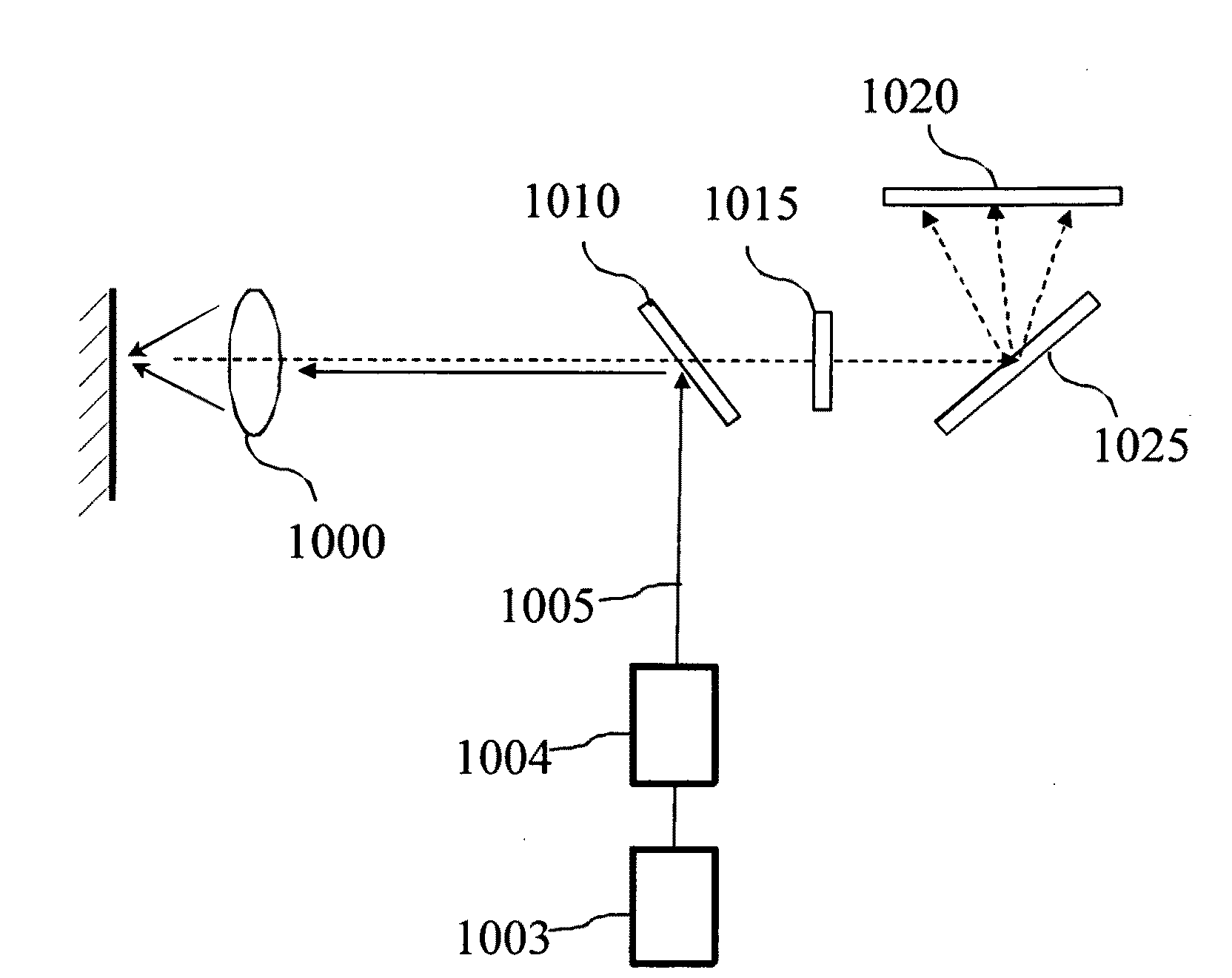
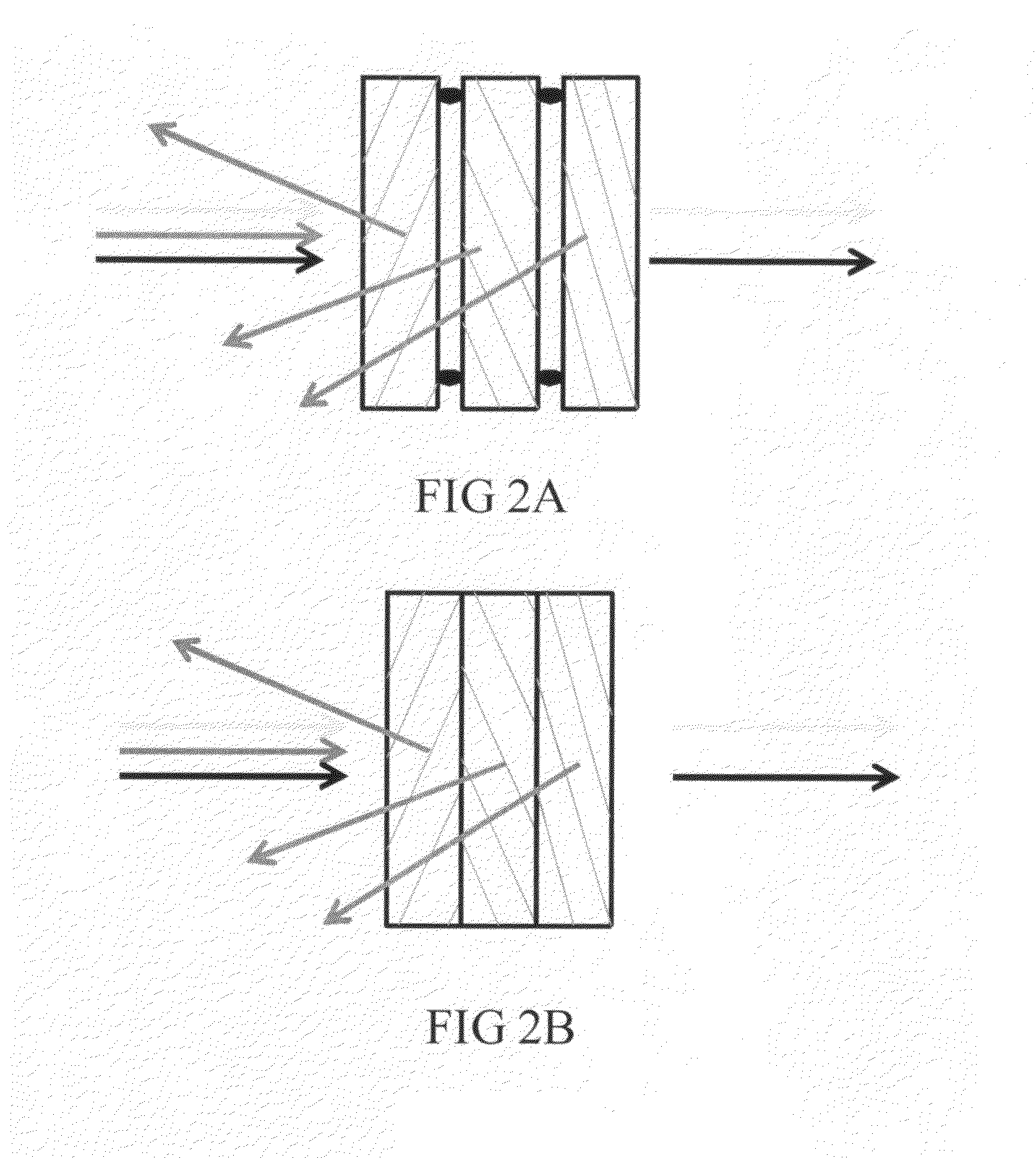
[0015]The invention disclosed here teaches methods to fabricate and utilize a non-dispersive holographic wavelength blocker to overcome all the limitations outlined above. The invention enables the observation of the Raman signal near the excitation wavelength (˜9 cm−1) with the compactness of standard thin film / holographic notch filter. The novelty is contacting several individual volume holographic blocking notch filter (VHBF) to form one high optical density blocking filter without creating the spurious multiple diffractions that yield unacceptable rejection ratios. Such ultra-narrow-band VHBF can be used in existing compact Raman instruments and thus will help bring high-end research to a greater number of users at a lower cost.

Problems solved by technology

However both notch filter technologies are limited to observing Raman spectral shift above approximately 350 cm−1.
However, there are several drawbacks to this approach:1. The alignment procedure is complicated and required for each VHG separately.2. The footprint is large (˜100 cm3) and as such not suitable to replace standard notch filters in existing Raman instruments.3. The surface of each VHG contributes to Fresnel reflection loss.4. Upon rotation of the assembly, the individual VHGs spectrally shift at different rates, thus reducing severely the optical density and broadening the overall blocker bandwidth.
The cascaded spectrometers are bulky (˜1 m2), expensive (˜$100K) and of moderate transmission (˜50%).

Method used


Image

  • Method and apparatus using volume holographic wavelength blockers
  • Method and apparatus using volume holographic wavelength blockers
  • Method and apparatus using volume holographic wavelength blockers

Examples


Embodiment Construction

[0029]In the following description of the present invention, reference is made to the accompanying drawings which form a part hereof, and in which is shown by way of illustration a specific embodiment in which the invention may be practiced. It is to be understood that other embodiments may be utilized and structural changes may be made without departing from the scope of the present invention.

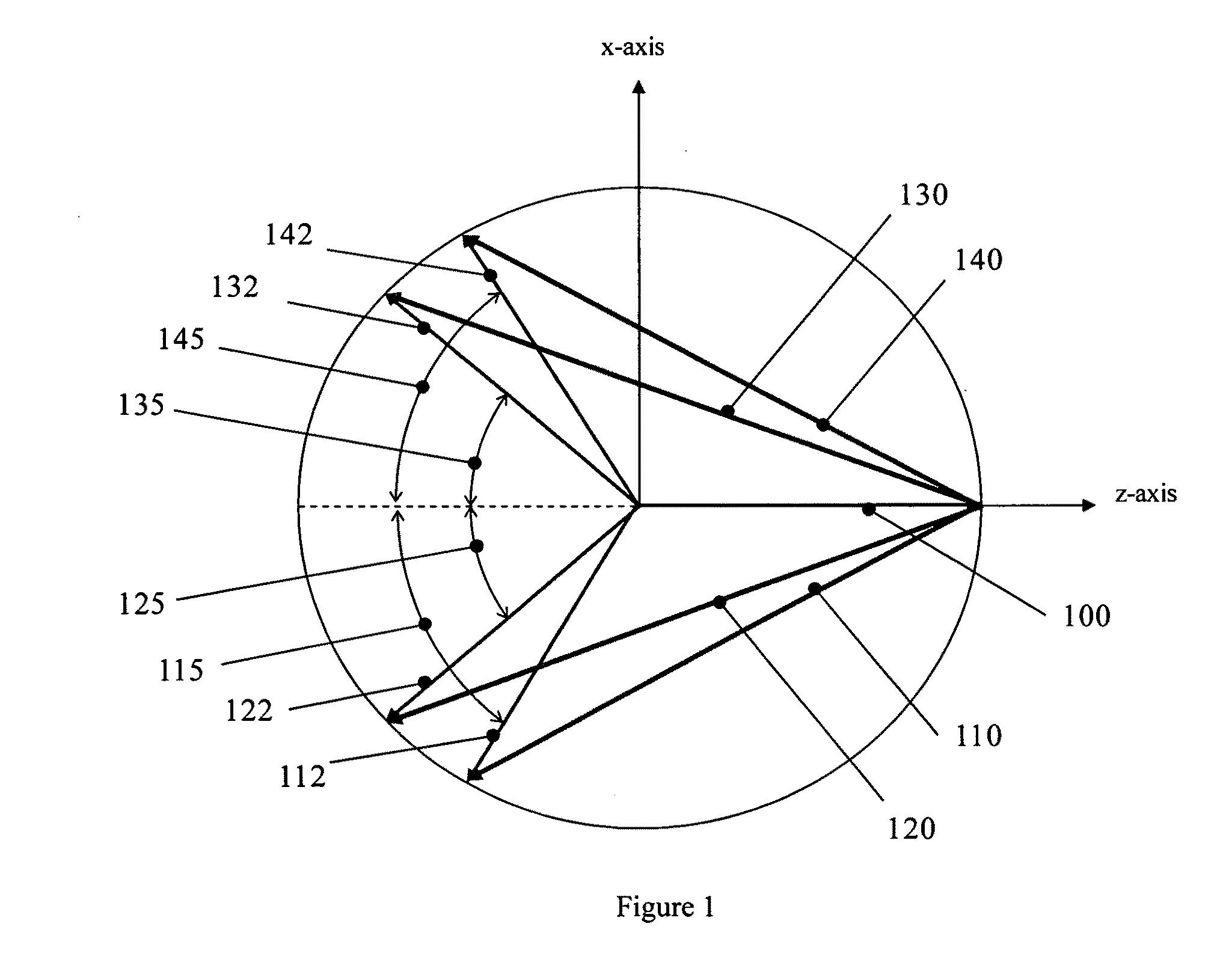
[0030]The notch wavelength λB of a reflective VHG is characterized by the grating period Λ and the angle of incidence Θ of the collimated illumination on the grating planes:

λB=λo·COS(Θ),   (1)

where λo=2·n·Λ is the anti-parallel diffraction wavelength where n the index of refraction. Identical reflection VHGs, i.e. VHGs characterized by the same grating period Λ and incidence angle Θ cannot simply be stacked since the diffracted beams will fulfill the Bragg condition for other VHGs in the stack. Double diffraction on individual VHGs will cause interference effects and prevent the optical densit...


PUM


Abstract

The invention disclosed here teaches methods to fabricate and utilize a non-dispersive holographic wavelength blocker. The invention enables the observation of the Raman signal near the excitation wavelength (˜9 cm−1) with the compactness of standard thin film / holographic notch filter. The novelty is contacting several individual volume holographic blocking notch filter (VHBF) to form one high optical density blocking filter without creating spurious multiple diffractions that degrade the filter performance. Such ultra-narrow-band VHBF can be used in existing compact Raman instruments and thus will help bring high-end research to a greater number of users at a lower cost.

Description

RELATED APPLICATION[0001]This patent application claims priority to provisional patent application 61 / 137,871 filed on Aug. 4, 2008 and incorporated by reference herein in its entirety.BACKGROUND OF THE INVENTION[0002]1. Field of the Invention[0003]The present invention relates to a method and apparatus for fabricating and using volume holographic wavelength blockers of high optical density and narrow bandwidth. Wavelength blockers are used to attenuate the signal of a pump source such as lasers while letting a scattering signal such as but not limited to fluorescence or Raman to go through. Thick reflective volume holographic elements (>typ. 0.1 mm thickness) have narrow rejection band but have limited attenuation of the order of optical density of 1 to 2. It is desirable to have a narrow spectral band rejection in conjunction with high attenuation reaching at least an optical density 6 for Raman spectroscopy for example.[0004]Portions of the disclosure of this patent document c...

Claims


Application Information

Patent Timeline
Patent Type & Authority Applications(United States)
IPC IPC(8): G01J3/44G02B5/32
CPCG01J3/02G02B5/32G01J3/44G01J3/0227G03H1/0248
Inventor MOSER, CHRISTOPHEHAVERMEYER, FRANK
Owner COHERENT INC
Learn More