Magnetic recording apparatus
a recording apparatus and magnetic technology, applied in the field of microwave assisted magnetic recording apparatus, can solve the problems of difficult achievement of microwave assisted magnetic recording, difficult to efficiently apply high-frequency magnetic field during recording with high density,
- Summary
- Abstract
- Description
- Claims
- Application Information
AI Technical Summary
Benefits of technology
Problems solved by technology
Method used
Image

Examples
first embodiment
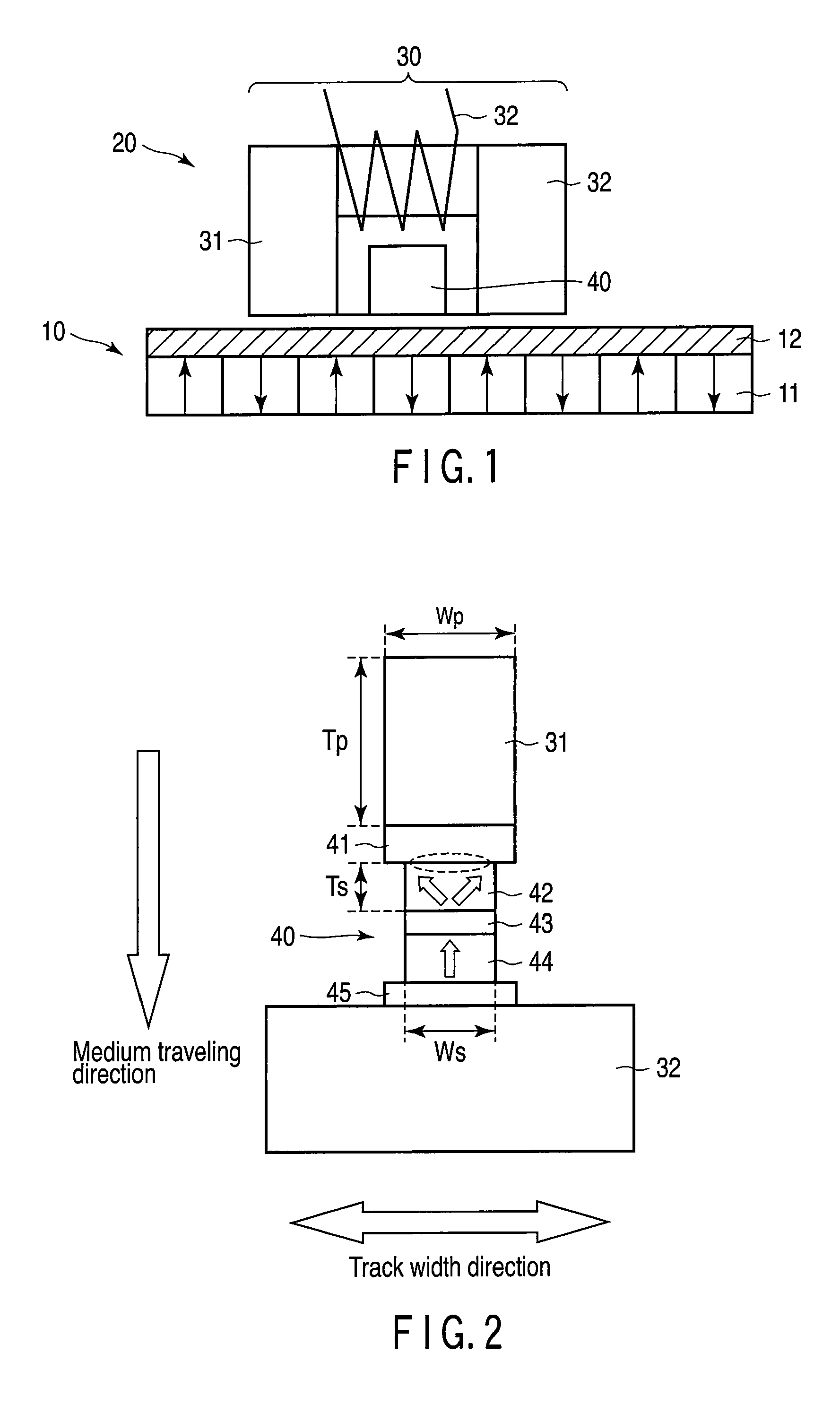
[0025]FIG. 1 is a cross-sectional view of a magnetic recording apparatus according to this embodiment. A magnetic recording medium 10 includes a hard magnetic recording layer 11 and a hard magnetic antenna layer 12 formed on a substrate (not shown). As will be described in detail later, a resonance frequency fa of the antenna layer 12 is lower than a resonance frequency fr of the recording layer 11. The recording layer 11 and the antenna layer 12 are ferromagnetically coupled. The recording layer 11 and the antenna layer 12 may be in direct contact with each other, and also may have a non-magnetic layer or a magnetic metal interposed therebetween. A magnetic recording head 20 disposed above the magnetic recording medium 10 has a write pole 30 and a spin torque oscillator (STO) 40. The write pole 30 includes a magnetic pole 31, a shield 32 and a coil 33 for exciting these components.
[0026]FIG. 2 is a plan view of the magnetic recording head 20 according to the embodiment as viewed fr...
second embodiment
[0060]A magnetic recording medium according to a second embodiment will be described.
[0061]FIG. 9A is a perspective view of an example of the magnetic recording medium according to the present embodiment. In FIG. 9A, dot-shaped antenna layers 12a divided into reversal units are formed on the recording layer 11 made of a continuous film. In other words, the antenna layer is processed into bit patterns. Note that in FIG. 9A, the magnetizations of the dot of one antenna layer 12a and the recording layer 11 thereunder are reversed in the case of a track width A, and the magnetizations of the dots of two antenna layers 12a and the recording layer 11 thereunder are reversed in the case of a track width B.
[0062]The antenna layers 12a divided into reversal units facilitate the magnetization reversal of the reversal unit of the recording layer 11 because of the effect of concentrating the magnetic flux from the magnetic recording head. On the other hand, since the magnetic volume of the reve...
third embodiment
[0065]A magnetic recording apparatus according to the present embodiment will be described.
[0066]FIG. 10A is a cross-sectional view of the magnetic recording apparatus according to the present embodiment. In FIG. 10A, dot-shaped antenna layers 12a divided into reversal units are formed on the recording layer 11 made of a continuous film. The area Aa, shown in FIG. 10B, of a head facing surface of the antenna layer 12a functioning as a reversal unit is smaller than the area of the air-bearing surface of the oscillation layer 42 of the spin torque oscillator. In this example, the area of a surface obtained by sectioning the antenna layer 12a in parallel to the head facing surface is constant no matter where the antenna layer 12a is sectioned in the thickness direction thereof. However, depending on the conditions, such as a manufacturing method, this area may not be constant. In such a case, the cross-sectional area of the head facing surface when sectioned at the center in the thickn...
PUM
| Property | Measurement | Unit |
|---|---|---|
| thickness | aaaaa | aaaaa |
| thickness Tp | aaaaa | aaaaa |
| size | aaaaa | aaaaa |
Abstract
Description
Claims
Application Information
 - R&D
- Intellectual Property
- Life Sciences
- Materials
- Tech Scout
- Unparalleled Data Quality
- Higher Quality Content
- 60% Fewer Hallucinations
Browse by: Latest US Patents, China's latest patents, Technical Efficacy Thesaurus, Application Domain, Technology Topic, Popular Technical Reports.
© 2025 PatSnap. All rights reserved.Legal|Privacy policy|Modern Slavery Act Transparency Statement|Sitemap|About US| Contact US: help@patsnap.com