
Lighting device comprising at least one LED

a technology of leds and light sources, which is applied in the direction of lighting and heating apparatus, instruments, condensers, etc., can solve the problems of complex structure, prior-art devices may not (easily) allow mixing of different led light within the device or display unit comprising the array of leds, etc., and achieves simple structure, low cost, and low cost

Inactive Publication Date: 2010-02-04
KONINKLIJKE PHILIPS ELECTRONICS NV
View PDF14 Cites 52 Cited by
  • Summary
  • Abstract
  • Description
  • Claims
  • Application Information

AI Technical Summary

Benefits of technology

[0004]It is an object of the invention to provide an alternative lighting device which preferably further obviates one or more of the drawbacks described above. In a specific embodiment, it is an object of the invention to provide a lighting device in which glare during use may be substantially absent or extremely low. In yet another specific embodiment, it is an object of the invention to provide a lighting device in which light of different LEDs within the lighting device can be mixed, thereby decreasing, for instance, the effect of “binning” and thus reducing the possible undesired effect, visible to an observer, that different LEDs may have undesired slightly different emission properties, such as especially slightly different colors, and / or allowing the use of LEDs with different colors while the light of the LEDs is well mixed.
[0007]The lighting device according to the invention has the advantage that it is a relatively simple system with relatively few optical components, which allows a high brightness device with substantially no glare. It is further possible to mix the light of different LEDs. It is even possible to obtain a lighting device in which, when in use, the individual LEDs are not visible anymore and the lighting device and its light is experienced as a kind of light tile. Furthermore, it is also possible to tune the amount of light directed to the front face, back face and side face directions.

Problems solved by technology

These prior-art lamps have one or more of the drawbacks that they have a complicated structure or use relatively complicated means to obtain a device that emits light in the required direction.
Furthermore, the prior-art devices may not (easily) allow mixing of the light of different LEDs within the device or display unit comprising the array of LEDs.

Method used


Image

  • Lighting device comprising at least one LED
  • Lighting device comprising at least one LED
  • Lighting device comprising at least one LED

Examples


example 1

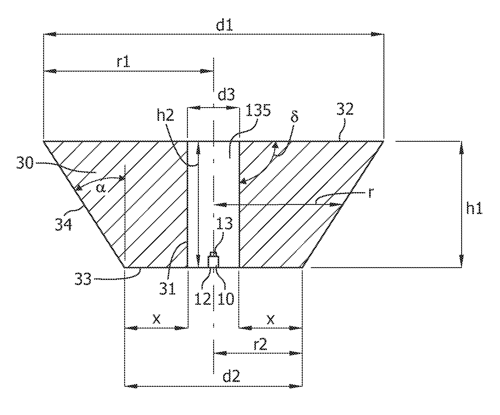
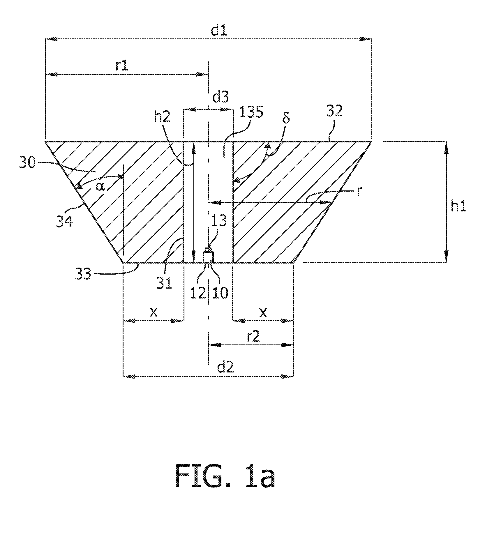
[0064]FIG. 5 shows the intensity distribution of a single LED (lambertian, 1 μm) installed in a fully transparent LED tile (100×200 mm2, thickness h1=h3(h2)=h4=h5=8 mm) having 8×4 LED positions. A truncated conelike element 30 was used as separate body 300 embedded in main body 200, as described above. A cone 30 with straight edges 34 was used; edges 24 were also straight; and a constant slit width w1 (approximately 100 μm) was applied; furthermore, recess 35 was cylindrical (as shown in the Figures). The length x was selected to be 3 mm, and a was varied. The upper curve shows the intensity as a function of γ (viewing angle) with α 32° (r2 / h1=0.375; h1=h3=h4; r1 / h=1.000), the lower curve (two maxima) with α 36.9° (r2 / h1=0.375; h1=h3=h4; r1 / h=1.125) and the lowest curve (about 5 maxima) with α 41.2° (r2 / h1=0.375; h1=h3=h4; r1 / h=1.250). It appears that the larger α, i.e. the broader the collimator 30 (with the same values for d3 (2.8 mm), h3 and x), the broader the light beam.

[0065]F...

example 2

[0067]A characteristic example of a light tile as shown in FIG. 4a is described below.

[0068]A number of lighting devices (a complete luminaire) were made with r1 / h1=1.125, r2 / h1=0.375, d3 / h1=0.35 and α=36.9°. Recess 35 has a cylindrical shape and slit 38 is a straight slit with a constant width w1 (approximately 100 μm). Top LEDs were used (blue LED+YAG:Ce), with a diameter of 2.6 mm of the emitting surface; the height h1=h3(h2)=h4=h5=8 mm. The pitch of the LEDs, i.e. the distance between the centers of one LED to the next was 25 mm (square arrangement). Each device (i.e. each tile) comprised 4*8 LEDs+collimators; each tile had dimensions of 100*200 mm2. A luminaire of 6 tiles in series (long sides next to each other) produced 1492 lm.


PUM


Abstract

The invention provides a lighting device comprising at least one LED and at least one collimator structure comprising the at least one LED. The invention especially relates to a lighting device comprising a plurality of such structures. The collimator in the collimator structure is made of a transparent material. In a specific embodiment, a transparent light tile is provided.

Description

FIELD OF THE INVENTION[0001]The present invention relates to a lighting device comprising at least one LED and at least one collimator structure comprising the at least one LED. The invention especially relates to a lighting device comprising a plurality of such structures.BACKGROUND OF THE INVENTION[0002]Lighting devices comprising a plurality of light-emitting diodes (LEDs) are known in the art. For instance, WO2006 / 045897 describes an array of light-emitting devices implemented in a single plate. The light-emitting device comprises a light-emitting diode and a reflecting surface. In this device, the light-emitting diode is adapted to emit a diverging light beam into a direction, and the reflecting surface is adapted to direct light emitted from the light-emitting diode substantially into this direction. Furthermore, US2005 / 0265029 (WO2005 / 119314) describes a light-emitting diode array which comprises an array of LEDs mounted on a substrate. The LEDs emit light in a direction whic...

Claims


Application Information

Patent Timeline
IPC IPC(8): F21V1/00
CPCF21V7/0091F21Y2101/02G02B6/0035G02B19/0028G09G3/3406G02B19/0066G02F1/133603F21Y2115/10
Inventor BOONEKAMP, ERIKVERBRUGH, STEFAN MARCUS
Owner KONINKLIJKE PHILIPS ELECTRONICS NV
Learn More