Closed-loop digital power control for a wireless transmitter

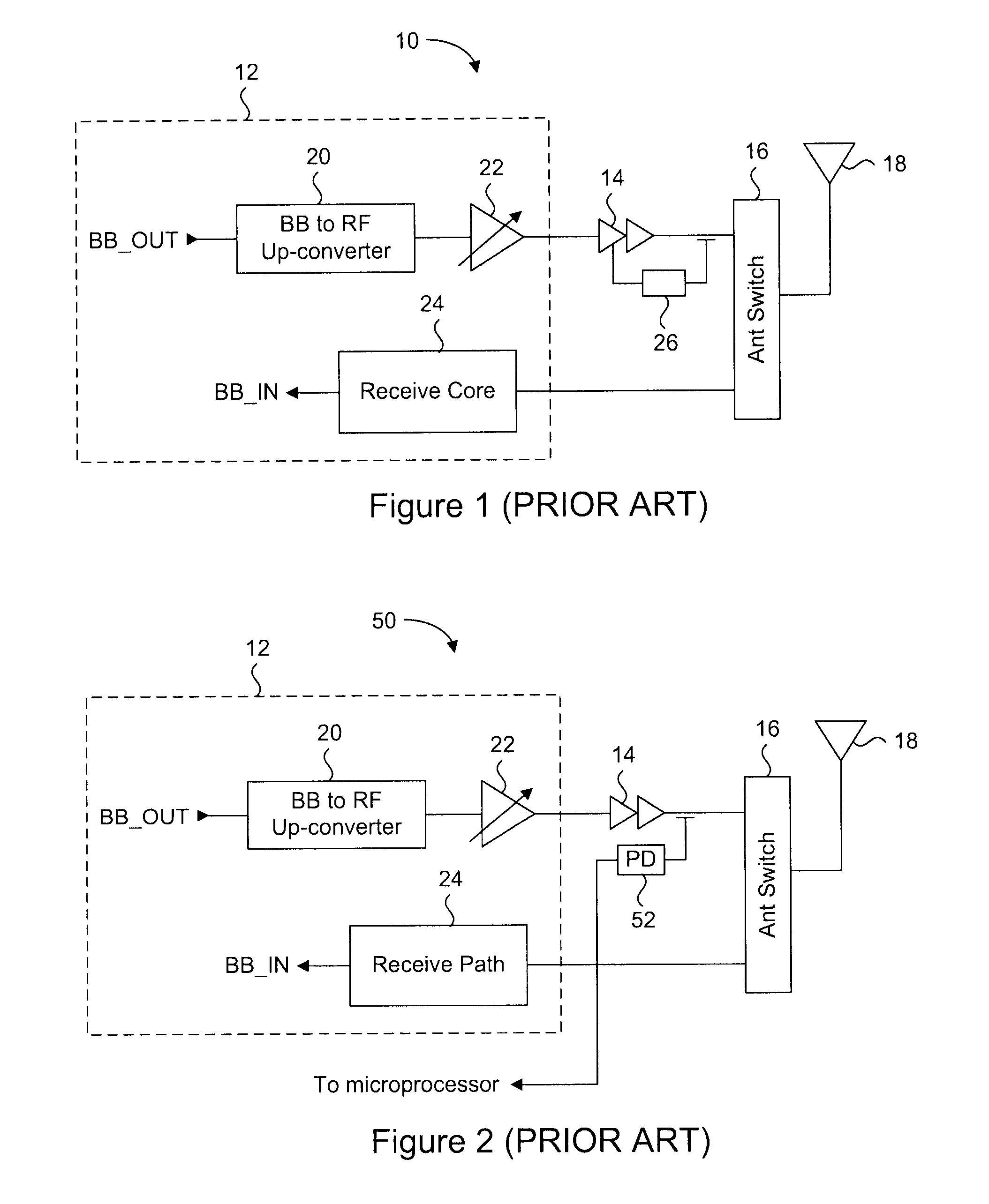
a closed-loop digital and wireless transmitter technology, applied in the field of wireless transceivers, can solve the problems of limiting the wireless device to that specific standard, the closed-loop power correction system shown in fig. 1 cannot be used for the standard required variable power output, and the performance of the circuit of the transmitter core will vary

Active Publication Date: 2010-02-04
ICERA CANADA ULC
View PDF9 Cites 59 Cited by
  • Summary
  • Abstract
  • Description
  • Claims
  • Application Information

AI Technical Summary

Benefits of technology

[0014]It is an object of the present invention to obviate or mitigate at least one disadvantage of previous closed loop power output correction systems.

Problems solved by technology

One of the problems with maintaining a constant transmit power output level is that the circuits of the transmitter core will have performance that varies over temperature and process technology.
This technique is sufficient for standards that require fixed output power levels, but then limits the wireless devices to that specific standard.
Therefore, the closed loop power correcting system shown in FIG. 1 cannot be used for standards required variable power output.
The problem with this system is that no accounting for process variation is provided because the characterized data is based on a nominal manufactured transceiver circuit.
It should be apparent to persons skilled in the art that characterization of each wireless device requires significant amounts of time.
The main problem with this solution is that the power detector is a discrete device whose characteristics will vary with temperature as well.
Another problem is that the base band processor will require an auxiliary analog to digital converter for converting the detected output power into a digital signal.
Unfortunately, temperature can change the ramping profile such that ramping will either be too fast or too slow.
A slow ramping of power results in insufficient data being sent to the base station as ramping has intruded into the data transmission time.
Too fast and too much data is spuriously transmitted into the air, which may violate certain governmental regulations, or specifications set by one or more wireless standards.
While this may reduce characterization time per wireless device, accuracy will be poor.

Method used


Image

  • Closed-loop digital power control for a wireless transmitter
  • Closed-loop digital power control for a wireless transmitter
  • Closed-loop digital power control for a wireless transmitter

Examples


Embodiment Construction

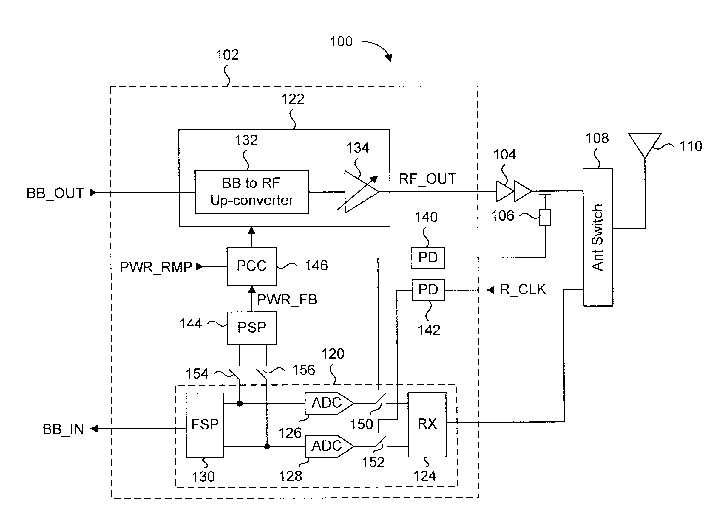
[0030]Generally, the present invention provides a closed loop power output calibration system for variable power output wireless devices. The wireless device includes a wireless transceiver having a transmit core coupled to a discrete power amplifier. Power detection circuitry formed in the wireless transceiver provides a detected power level of the power amplifier, and a reference power level, both of which are converted to digital signals using existing I and Q signal analog to digital converters in the receiver core. The digital signals are processed to cancel power distortion and temperature effects to provide a resulting power feedback signal. The power feedback signal is compared to gain signals corresponding to a desired power output level, and corrective control signals are generated. The corrective control signals can adjust the gain of a variable gain amplifier coupled to the power amplifier, and / or the gain of an input signal prior to amplification by the variable gain am...


PUM


Abstract

A closed loop power output calibration system for variable power output wireless devices. The wireless device includes a wireless transceiver having a transmit core coupled to a discrete power amplifier. Power detection circuitry formed in the wireless transceiver provides a detected power level of the power amplifier, and a reference power level, both of which are converted to digital signals using existing I and Q signal analog to digital converters in the receiver core. The digital signals are processed to cancel power distortion and temperature effects to provide a resulting power feedback signal. Corrective control signals are generated in response to the power feedback signal relative to a desired power output level. The gain in the transmit core is then adjusted in response to the corrective control signals such that the power amplifier outputs the target output power level.

Description

CROSS REFERENCE TO RELATED APPLICATIONS[0001]This application claims the benefit of priority of U.S. Provisional Patent Application No. 60 / 871,306 filed on Dec. 21, 2006, the contents of which are incorporated herein by reference in its entirety.FIELD OF THE INVENTION[0002]The present invention relates generally to wireless transceivers. More particularly, the present invention relates to output power control in the transmit path of a wireless transceiver.BACKGROUND OF THE INVENTION[0003]Wireless devices have been in use for many years for enabling mobile communication of voice and data. Such devices can include mobile phones and wireless enabled personal digital assistants (PDA's) for example. The transmission and reception of voice and data information by the wireless device is conducted with a base station, and in accordance with a particular standard, such as the Global System for Mobile Communications (GSM) standard.[0004]The GSM standard dictates that wireless devices must tra...

Claims


Application Information

Patent Timeline
Patent Type & Authority Applications(United States)
IPC IPC(8): H04B1/38
CPCH04B2001/0416H03G3/3047
Inventor BELLAOUAR, ABDELLATIFMANKU, TAJINDER
Owner ICERA CANADA ULC
Why Eureka
Try Eureka