
Image compression and decompression

a compression and decompression technology, applied in the field of image compression and decompression, can solve the problems of lossy compression methods, and limited reduction of compression artefacts after filtering, so as to reduce bandwidth the effect of needing

Active Publication Date: 2010-02-04
KONINKLIJKE PHILIPS ELECTRONICS NV
View PDF14 Cites 99 Cited by
  • Summary
  • Abstract
  • Description
  • Claims
  • Application Information

AI Technical Summary

Benefits of technology

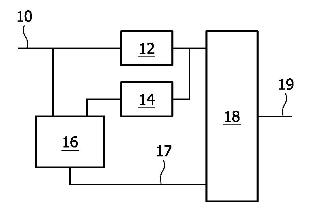
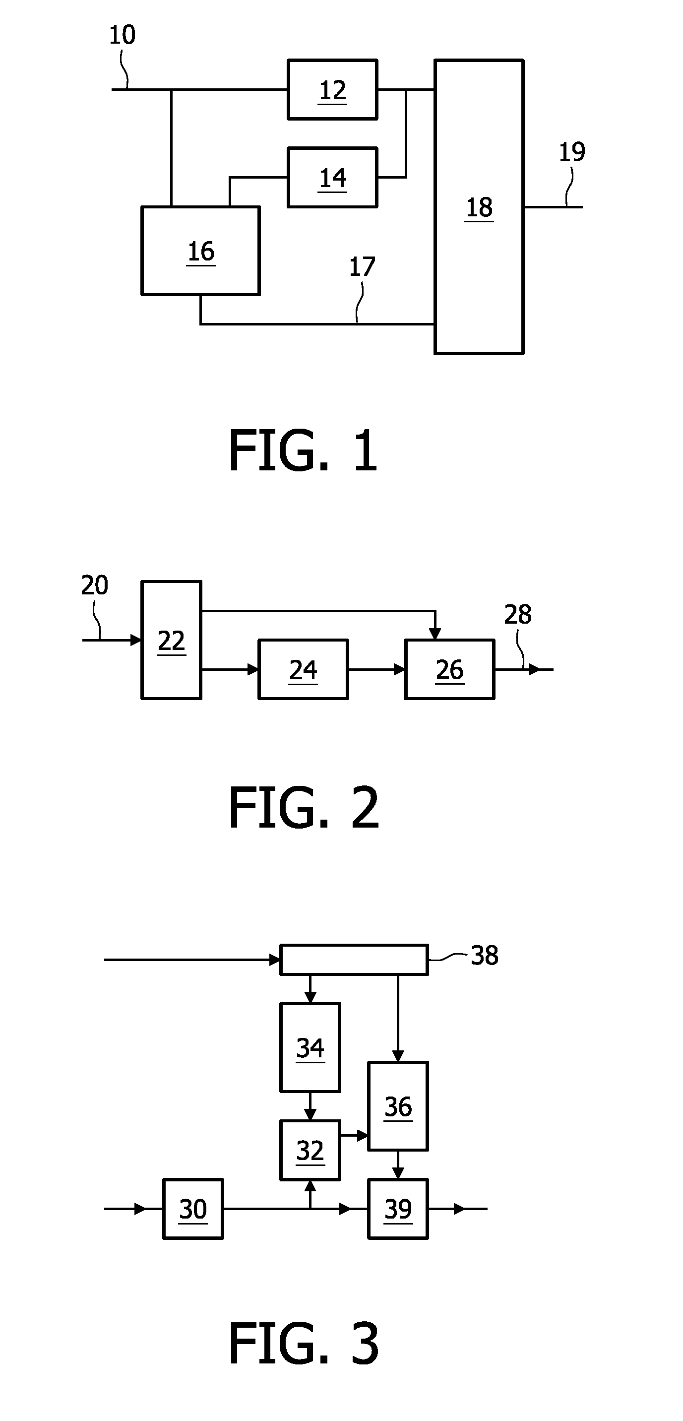
[0012]A compression apparatus according to claim 18 is provided. This compression apparatus selects the control parameter sets for different classes and adds them to the compressed image signal. In an embodiment the compression apparatus also selects a class definition dependent on the content of the image and adds it to the compressed image signal. The class definition may comprise for example representative vectors of pixel values in windows of the decompressed image. In an embodiment the plurality control parameter sets are computed in common for a plurality of input images. In this way the control parameter set can be reused for different images. This reduces bandwidth needed for the compressed signal. The control parameter sets may be selected dependent on a difference between the input image and a decompressed image defined by the decompressed image signal, so as to define post-processing operations that define this difference.

Problems solved by technology

These lossy compression methods introduce artefacts, i.e. differences between original images and reconstructed images that are obtained after compression and decompression.
Unfortunately, this type of post-filtering only provides a limited reduction of compression artefacts.

Method used


Image

  • Image compression and decompression
  • Image compression and decompression
  • Image compression and decompression

Examples


example a

[0186] not exact but similar worm-like structures: the transformation of a “not exact rotation” can be done e.g. like this: classify the pixels in a block into dark and bright [e.g. above block average], and use a “chain orientation code” to test similarity: E.g.: If the directional change is in the same compass direction and the, length differs not more than 1 pixel for each oriented run of pixels (e.g. 2 vs. 3 pixel starting segment), the pattern may be considered similarly, and treated with a similar filter (e.g. certain blur Kernel size).

[0187]Example B: One could also normalize the (grey value) height of an edge (although in some filter cases [e.g. filter implements an edge strength change] it may be wiser to adapt the filter also to the height of the edge, but in those cases one could e.g. classify the edge step height in a number of subclasses (strong, medium, minor edge).

[0188]Example C gives another example which can be used e.g. to process (pseudo) periodic textures (e.g. ...


PUM


Abstract

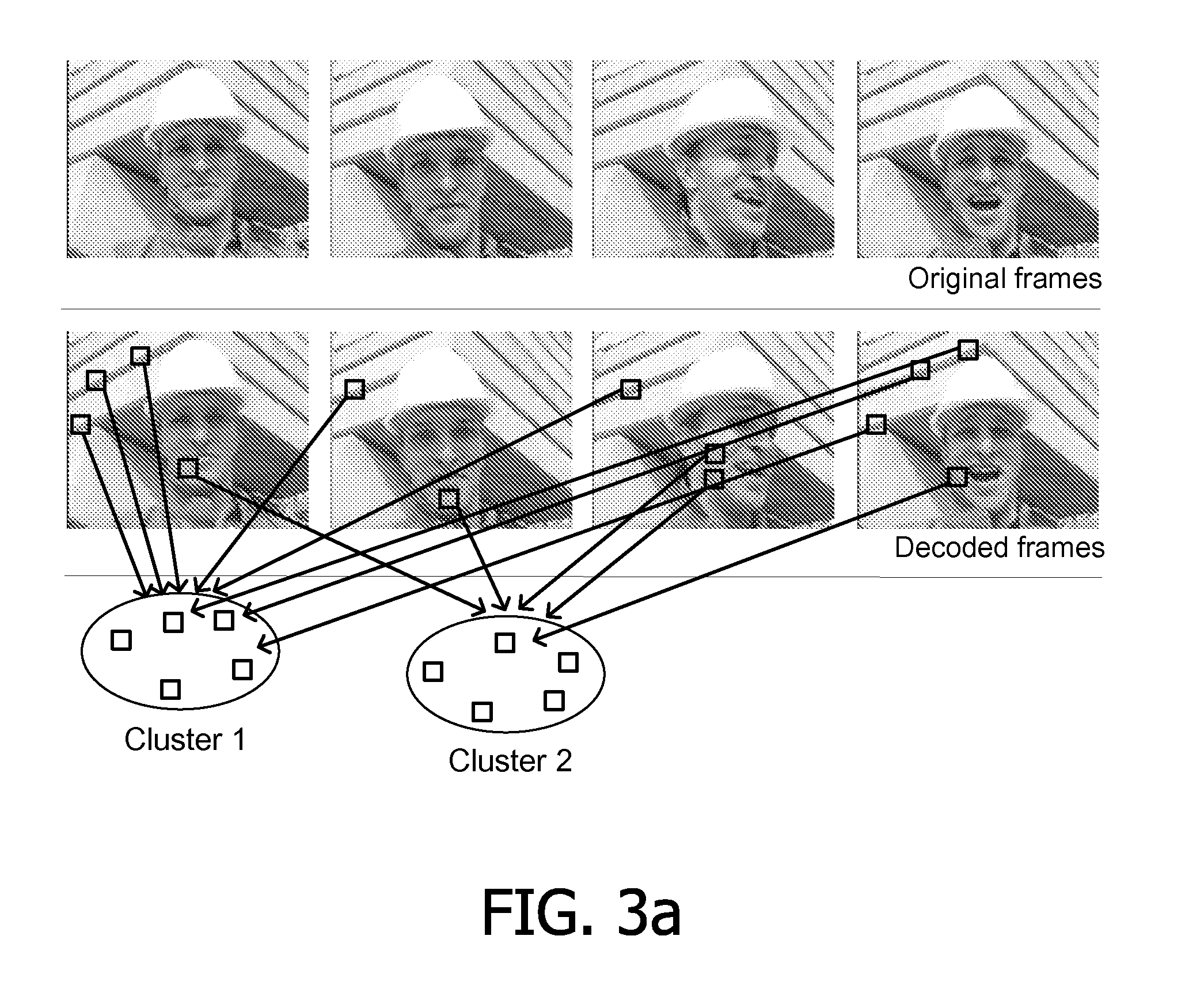
Clusters of pixels are defined for use in image compression and decompression. The image information used to define the clusters may include pixel values at predetermined positions relative to a pixel or related motion vectors, gradients, texture etc. During compression of images the image information relative to pixels is examined to determine the cluster to which it belongs. Thus pixels can be classified according to the cluster for their image information. In an embodiment the definitions of the clusters are selected dynamically, dependent on image content. For each cluster a control parameter set is computed for a post-processing operation, such as filter coefficients for filtering or statistical data for locally generating texture. The control parameter set is selected dependent on the image content so that, when the post-processing operation is applied to the image after decompression it will improve image quality for the pixels that are classified as belonging to the cluster. The compressed image and the control parameter sets are transmitted to a decompression apparatus. Upon decompression, the image information that represents the decompressed image is examined to classify pixels according to the clusters and the different control parameter sets for the selected clusters are used to control post-processing at the locations of the pixels.

Description

FIELD OF THE INVENTION[0001]The invention relates to methods and apparatuses for image compression and decompression.BACKGROUND OF THE INVENTION[0002]Methods of lossy image compression are known, both in the context of video compression and for individual images. The dominant examples are the methods defined in the various MPEG and JPEG compression / decompression standards, which include coarse quantization of image data. These lossy compression methods introduce artefacts, i.e. differences between original images and reconstructed images that are obtained after compression and decompression.[0003]A method of reducing these differences has been described in a publication titled “Post filter SEI message for 4:4:4 coding” by S. Wittmann and T. Wedi, at the 18th meeting of the Joint Video Team (JVT) of ISP / IEC MPEG & ITU-T VCEG (document number JVT S030).[0004]In this publication it is proposed to add messages to an MPEG video stream that define the filter coefficients for a FIR (Finite...

Claims


Application Information

Patent Timeline
IPC IPC(8): H04N7/26G06K9/46H04N19/89
CPCG06T9/00H04N19/46H04N19/117H04N19/86H04N19/182H04N19/179H04N19/187H04N19/137H04N19/85
Inventor ZUO, FEIDE WAELE, STIJNBRULS, WILHELMUS HENDRIKUS ALFONSUSHINNEN, KAREL JOHANNES GERHARDUSVERBERNE, MICHAEL
Owner KONINKLIJKE PHILIPS ELECTRONICS NV
Learn More