System and method for tracking movement of joints

a technology of joints and joints, applied in the field of tracking the movement of objects, can solve the problems of affecting the wearability of the subject's suit, requiring the attachment of a costly and cumbersome marker to the object, and affecting the effect of movement, so as to achieve the effect of convenient and cost-effective us

Inactive Publication Date: 2010-02-04
THINK THING
View PDF5 Cites 7 Cited by
  • Summary
  • Abstract
  • Description
  • Claims
  • Application Information

AI Technical Summary

Benefits of technology

[0007]Approaches are provided that track the movement of joints in objects. These approaches do not require the use and wearing of markers or other equipment that can be used to demarcate joints and, in many cases, are accomplished with the use of an image capture device. The approaches described herein can be used in both open and confined spaces, and are cost effective to implement.
[0014]Thus, approaches are provided that track the movement and position of joints. These approaches can be utilized to track the movement of any type of joint (e.g., human, mechanical) in any type of space (e.g., open, confined). These approaches are also easy and cost effective to use, for example, sometimes utilizing only a single camera. These approaches are also user-friendly, for instance, not requiring the wearing of uncomfortable items (e.g., body suits) or the attachment of markers.

Problems solved by technology

Unfortunately, various problems exist with all of the above-mentioned marker-based approaches.
For instance, the use of markers requires that a costly and cumbersome marker be attached to the object.
The markers must be physically fixed to the object and can often impair movement.
In many cases (such as in entertainment applications), the subject (e.g., an actor or actress) must wear a suit that is attached to the marker and the suit can be hot and uncomfortable for the subject to wear.
Visual approaches were expensive to implement in many areas where objects moved (e.g., open areas).
In these systems, the cameras were usually fixed thereby limiting the area of possible motion of the subject.
Inertial systems were highly inaccurate.
As for mechanical approaches, the exoskeleton was typically cumbersome and uncomfortable to wear.
Additionally, the range of motion was limited and the exoskeleton could not mimic the exact movement of the subject.

Method used


Image

  • System and method for tracking movement of joints
  • System and method for tracking movement of joints
  • System and method for tracking movement of joints

Examples


Embodiment Construction

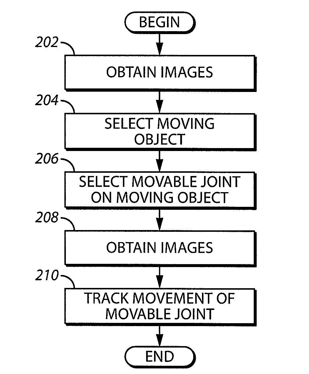
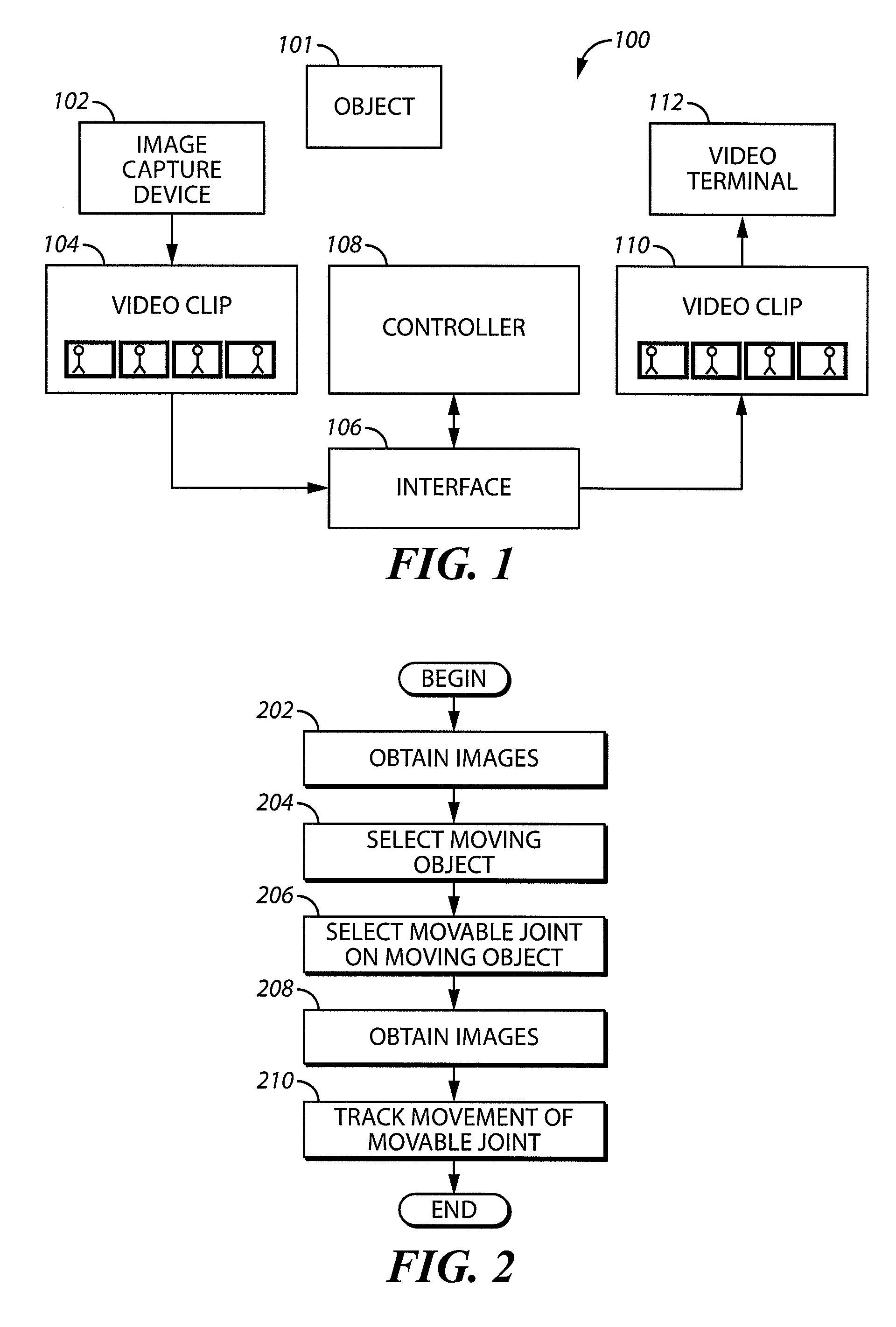
[0027]Referring now to FIG. 1, a system 100 for tracking joints of an object is described. The system 100 includes an image capture device 102, which supplies a video clip (or series of image frames) 104 of an object 101 to an interface 106. The interface 106 is coupled to a controller 108. The controller creates and the interface transmits a modified video clip 110 for display to a user on a display 112.

[0028]The image capture device 102 may be any suitable device that is used to acquire images. In this respect it may be a video camera, a digital camera, or a camera on a satellite. Other types of cameras or image capture devices (e.g., using other technologies such as ultrasound, infrared) may also be used.

[0029]The interface 106 is any type of device or combination of devices that utilizes any combination of hardware and programmed software to convert signals between the different formats utilized by the image capture device 102, controller 108, and display 112. For example, the i...


PUM


Abstract

A first image is obtained. At least one moving object indicated by the at least one image is selected. At least one joint that is associated with the at least one moving object is identified. At least one second image including the at least one moving object with the at least one joint is obtained and the movement of the at least one joint is tracked in a three-dimensional space.

Description

RELATED APPLICATION[0001]“System and Method for Visually Representing an Object to a User” by Munish Sikka having Attorney's Docket No. 90589 being filed on the same day as the present application, the contents of which are incorporated herein by reference in their entirety.FIELD OF THE INVENTION[0002]The field of the invention relates to tracking the movement of objects (e.g., inanimate and living) and, more specifically, to tracking the movement of the joints of objects.BACKGROUND OF THE INVENTION[0003]Motion capture techniques have been used in various fields to track moving objects. For example, military organizations have used motion capture techniques to track moving objects targeted by missiles. In another example, doctors and other medical professionals have used motion capture techniques to analyze the gait of human subjects. In still another example, the entertainment industry has used these techniques to capture the motion of subjects for use in films.[0004]The above-ment...

Claims


Application Information

Patent Timeline
Patent Type & Authority Applications(United States)
IPC IPC(8): G06K9/00
CPCG06K9/00335G06T2207/30196G06T2207/20164G06T7/2033G06T7/246G06V40/20
Inventor SIKKA, MUNISH
Owner THINK THING
Why Eureka
Try Eureka