Channel Wavelength Assignment With Transient Reduction

a wavelength assignment and transient reduction technology, applied in the field of optical telecommunications networks, can solve the problems of unsatisfactory utilization of ulr in point-to-point network architecture, unsatisfactory utilization of ulr, and reduction of node complexity, and consequently network cost, so as to reduce the cost of network maintenance and operation, optimize the wavelength selection process, and reduce the effect of additional costs

Inactive Publication Date: 2010-02-04
ALCATEL LUCENT SAS
View PDF1 Cites 16 Cited by
  • Summary
  • Abstract
  • Description
  • Claims
  • Application Information

AI Technical Summary

Benefits of technology

[0019]Advantageously, provision of wavelength selection rules block enables addition of new rules to the existing ones, as well as rule changes. Furthermore, organizing the wavelengths into static wavelength bins allows manipulation of these bins as requested by a particular rule or set of rules. The bins may be organized based on a certain wavelength natural performance parameter (e.g. reach, or cost), fiber type and the wavelength plan (density, L-band or C-band). This enables the wavelength selection with various degrees of sophistication, and also adds flexibility to the process, in that it enables steering the selection for obtaining a desired mode of operation on the network. Still further, user-specific rules may be designed and used when / if required.
[0020]Use of wavelength bins and wavelength selection rules enables optimization of the wavelength selection process with minimal additional costs, since no new hardware is necessary. The particular optimization of the present invention biases the channel (wavelength) selection to increase operating margins with regard to Raman transient immunity.

Problems solved by technology

As a result, the advantages of the ULR cannot be fully exploited in point-to-point network architectures.
Reduction of the regeneration sites dramatically reduces the node complexity, and consequently the network cost.
Also, a close spacing between the channels creates an amplification effect that results in the spectrum of the WDM signal being undesirable tilted, the tilt increasing with the signal power.

Method used


Image

  • Channel Wavelength Assignment With Transient Reduction
  • Channel Wavelength Assignment With Transient Reduction
  • Channel Wavelength Assignment With Transient Reduction

Examples


Embodiment Construction

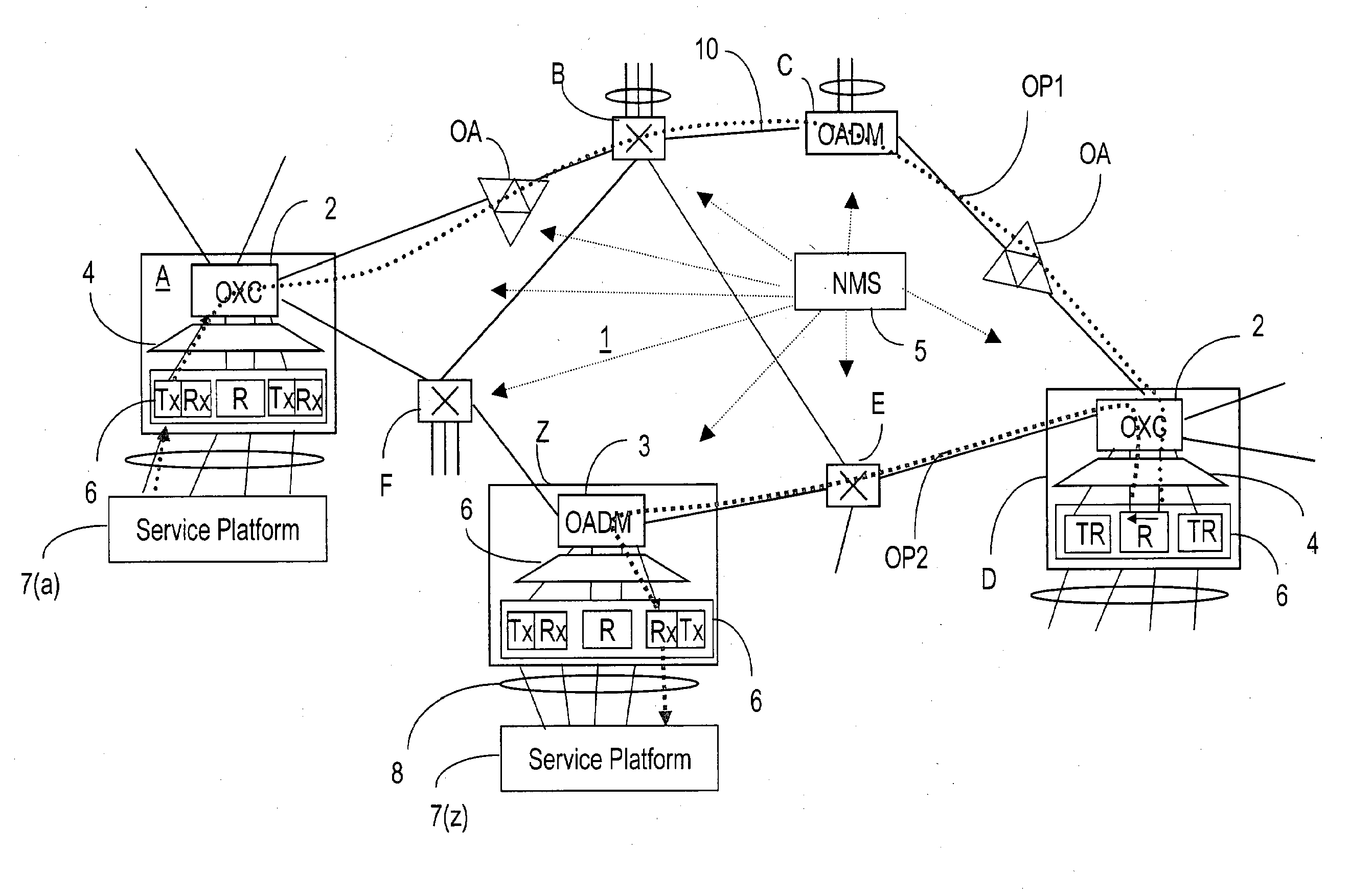
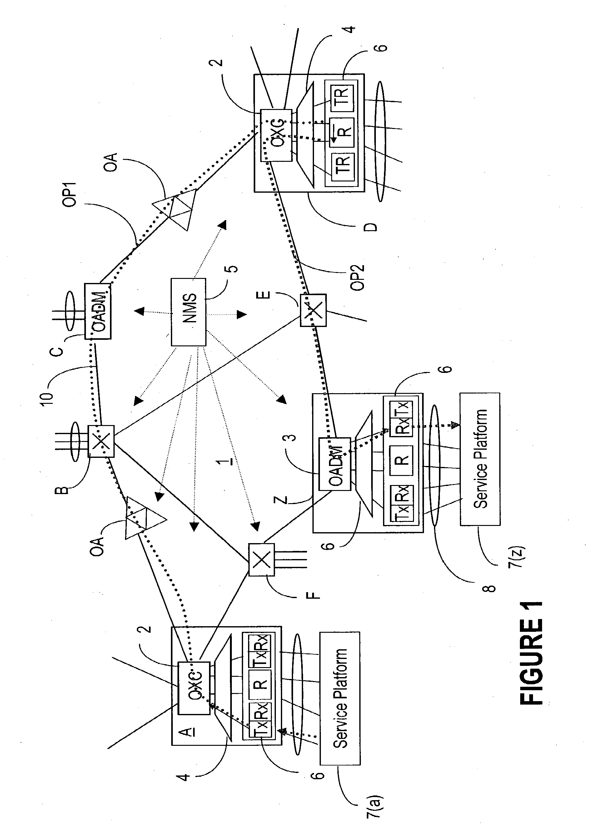
[0027]FIG. 1 shows an example of a photonic network 1 to which the present invention applies. As shown and described in the parent Patent Application Docket 1021US, network 1 comprises bidirectional fiber links 10 connecting a plurality of flexibility sites, which are nodes A, B, C, D, E, F, Z in this example. The nodes could be switching nodes A, B, D, E, F, or OADM (optical add / drop multiplexing) nodes C, Z. User traffic 8, originating and terminating on a service platform 7 (e.g. a router, an ATM switch, an EXC, etc.), accesses network 1 at a switching node or an OADM node, also called a flexibility site.

[0028]A flexibility site or node of agile network 1 may be partitioned into the following building blocks:

[0029]a) Wavelength switches 2 and OADMs 3, which provide optical passthrough, (bypassing OEO conversions), and optical add / drop of the local traffic from / to the service platform 7.

[0030]b) An electro-optics interface 6, that performs on / off ramp of client signals onto / from t...


PUM


Abstract

In an automatically switched optical network operating according to a wavelength plan, the wavelengths are assigned to an optical path based on availability, performance and SRS wavelength coupling reduction. First, the wavelengths are grouped in static bins based on their reach versus cost performance, and each bin assumes a ΔQ of a middle wavelength. Then, the bins are moved into subsets of dynamic bins, constructed using bin constraints that account for the particulars of the respective optical path. The path is characterized taking into account the wavelength currently accessing at the end nodes, and the wavelength tandeming through the end nodes. Wavelength selection starts with the bins that satisfy the maximum number of constraints, and the wavelengths are checked sequentially against wavelength constraints; relaxed constraints are also applied when it is not possible to exactly satisfy one or more constraints.

Description

PRIORITY PATENT APPLICATION[0001]Continuation in Part of U.S. patent application Ser. No. 09 / 909,265 “Wavelength Routing and Switching Mechanism for a Photonic Transparent Network” (Smith et al.) filed Jul. 19, 2001 and assigned to Innovance, Inc., Docket 1021US.RELATED PATENT APPLICATIONS[0002]U.S. patent application Ser. No. 10 / 017,833 for “Wavelengths Assignment in an Optical WDM Network” (Solheim et al.) filed April Dec. 12, 2001, and assigned to Innovance, Inc., Docket 1011U.S.[0003]U.S. patent application Ser. No. 10 / 128,092 for “Dynamic Assignment of Wavelengths in Agile Photonic Networks” (Kotikalapudi et al.) filed Apr. 23, 2002, and assigned to Innovance, Inc., Docket 1046US.[0004]These patent applications are incorporated herein by reference.FIELD OF THE INVENTION[0005]The invention resides in the field of optical telecommunications networks, and is directed in particular to channel wavelength assignment with transient reduction.BACKGROUND OF THE INVENTION[0006]Advances i...

Claims


Application Information

Patent Timeline
Patent Type & Authority Applications(United States)
IPC IPC(8): H04J14/02
CPCH04J14/0221H04J14/0284H04J14/0246H04J14/025H04J14/0257H04Q2011/0075H04J14/0271H04J14/0227H04Q11/0005H04Q11/0062H04J14/0269
Inventor GUY, JOHN PETERROORDA, PETER DAVIDSOLHEIM, ALAN GLENJONES, KEVAN PETERFRIESEN, GREG PETER
Owner ALCATEL LUCENT SAS
Why Eureka
Try Eureka