Compressor blade leading edge shim and related method

a technology of compressor blades and leading edges, applied in the field of turbine technology, can solve the problems of high cost of repair and/or replacement of damaged turbine blades, high cost of replacement, and high cost of turbine blades

Inactive Publication Date: 2010-02-04
GENERAL ELECTRIC CO
View PDF19 Cites 33 Cited by
  • Summary
  • Abstract
  • Description
  • Claims
  • Application Information

AI Technical Summary

Problems solved by technology

Compressor blade leading edge erosion / corrosion is a common problem in turbine engines.
Turbine blades, and particularly the leading edges of the turbine compressor blades or airfoils, are particularly susceptible to erosion and / or corrosion resulting from exposure to harsh environments.
Repair and / or replacement of damaged turbine blades requires costly downtime that may not coincide with normal service intervals.

Method used


Image

  • Compressor blade leading edge shim and related method
  • Compressor blade leading edge shim and related method
  • Compressor blade leading edge shim and related method

Examples


Embodiment Construction

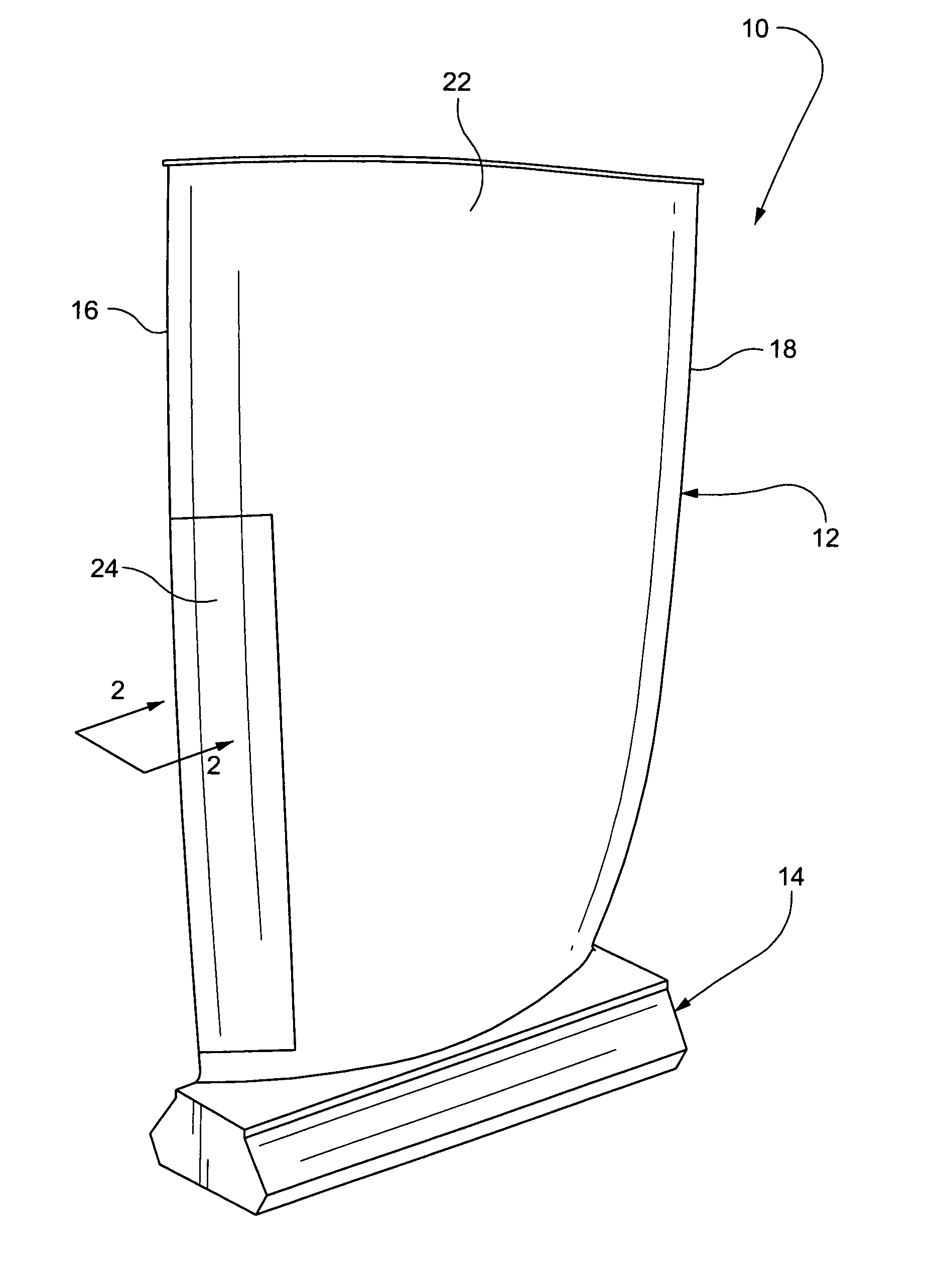
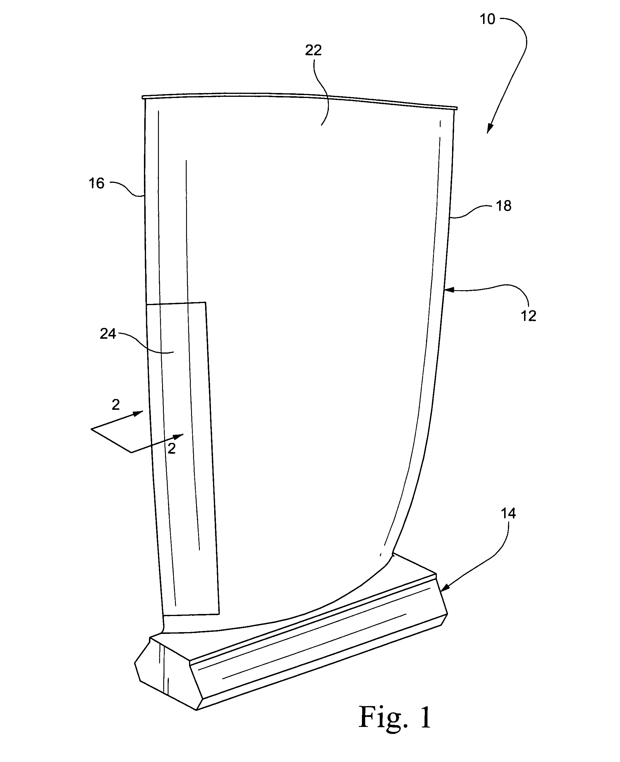
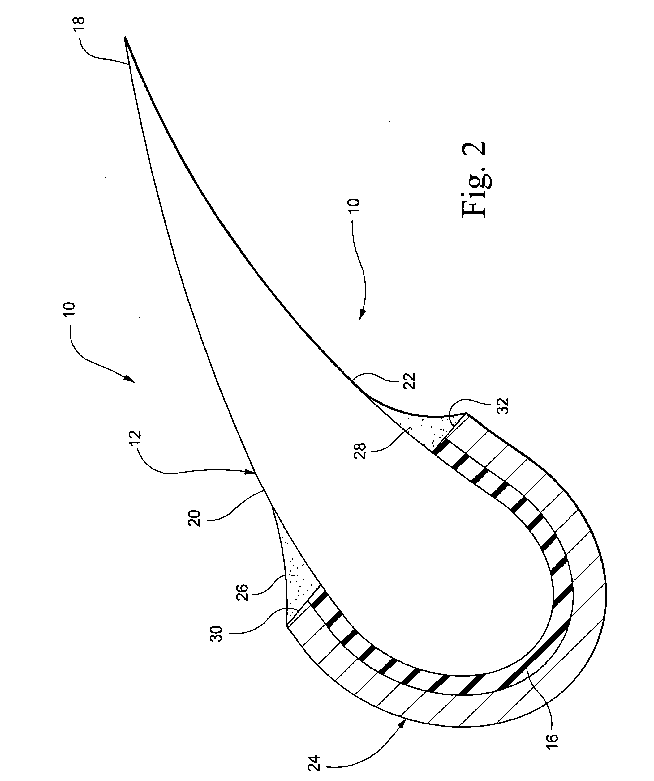
[0009]With reference to FIG. 1, a vane or blade 10, e.g., a turbine compressor blade, includes an airfoil portion 12 and a dovetail mounting portion 14. The airfoil portion 12 has a leading edge 16, a trailing edge 18, a pressure side 20 and a suction side 22.

[0010]It is the leading edge 16 that is most susceptible to erosion and / or corrosion due to incoming air flow (containing, for example, dry particles, salt fog, etc.) at the compressor inlet.

[0011]In accordance with a non-limiting exemplary embodiment of this invention, one or more shims 24 may be applied to the leading edge 16 of the airfoil portion. With further reference to FIG. 2, the shim 24 substantially encloses the leading edge 16, extending into both the pressure and suction sides 20, 22 of the airfoil. Note that in FIG. 2, the shim is shown in greatly exaggerated scale simply to facilitate an understanding of the invention. One shim may extend along part or substantially the entire length of the leading edge, or alter...


PUM

PropertyMeasurementUnit
thickaaaaaaaaaa
thicknessaaaaaaaaaa
thicknessaaaaaaaaaa

Abstract

A method of improving an erosion resistance at the leading edge of a compressor blade includes: a) cleaning a leading edge portion of the compressor blade airfoil; and b) attaching one or more erosion or corrosion-resistant shims to the leading edge portion.

Description

BACKGROUND OF THE INVENTION[0001]This invention relates generally to turbine technology and, more specifically, to an article and a method for mitigating damage caused by compressor blade leading edge erosion and / or corrosion.[0002]Compressor blade leading edge erosion / corrosion is a common problem in turbine engines. Turbine blades, and particularly the leading edges of the turbine compressor blades or airfoils, are particularly susceptible to erosion and / or corrosion resulting from exposure to harsh environments. Repair and / or replacement of damaged turbine blades requires costly downtime that may not coincide with normal service intervals.[0003]It would be advantageous, therefore, to develop techniques or processes to mitigate the incidence or damage caused by erosion and / or corrosion of blade leading edges.BRIEF DESCRIPTION OF THE INVENTION[0004]In accordance with one exemplary but nonlimiting embodiment, the invention relates to a compressor blade comprising an airfoil portion ...

Claims


Application Information

Patent Timeline
Patent Type & Authority Applications(United States)
IPC IPC(8): F04D29/38
CPCF01D5/005F01D5/28F04D29/023Y10T29/49337F05D2260/95F05D2230/80F04D29/321F04D29/324F05D2240/303F05D2230/23F05D2300/2284
Inventor SCHAEFFER, JON C.PABLA, SURINDER S.HELMICK, DAVID A.ROBERTS, JEFFREY
Owner GENERAL ELECTRIC CO
Why Eureka
Try Eureka