Rotor blade extension portion having a skin located over a framework

a technology of extension portion and framework, which is applied in the direction of propellers, propulsive elements, water-acting propulsive elements, etc., can solve the problems of framework and skin of the extension portion having some potential to deflect, and achieve the effect of efficient transmission of structural loads and easy transmission

Active Publication Date: 2010-02-04
VESTAS WIND SYST AS
View PDF23 Cites 19 Cited by
  • Summary
  • Abstract
  • Description
  • Claims
  • Application Information

AI Technical Summary

Benefits of technology

[0042]Buckling represents one of the primary modes of failure of a conventional rigid skin of a turbine blade and buckling is avoided when a membrane is used, as the compressive loads are not sustained.
[0043]By “structurally coherent” we mean that the associated component, here the blade portion of the rotor blade, ...

Problems solved by technology

If a rotor blade to which the extension portion is connected experiences extreme loading, for example ...

Method used


Image

  • Rotor blade extension portion having a skin located over a framework
  • Rotor blade extension portion having a skin located over a framework
  • Rotor blade extension portion having a skin located over a framework

Examples


Embodiment Construction

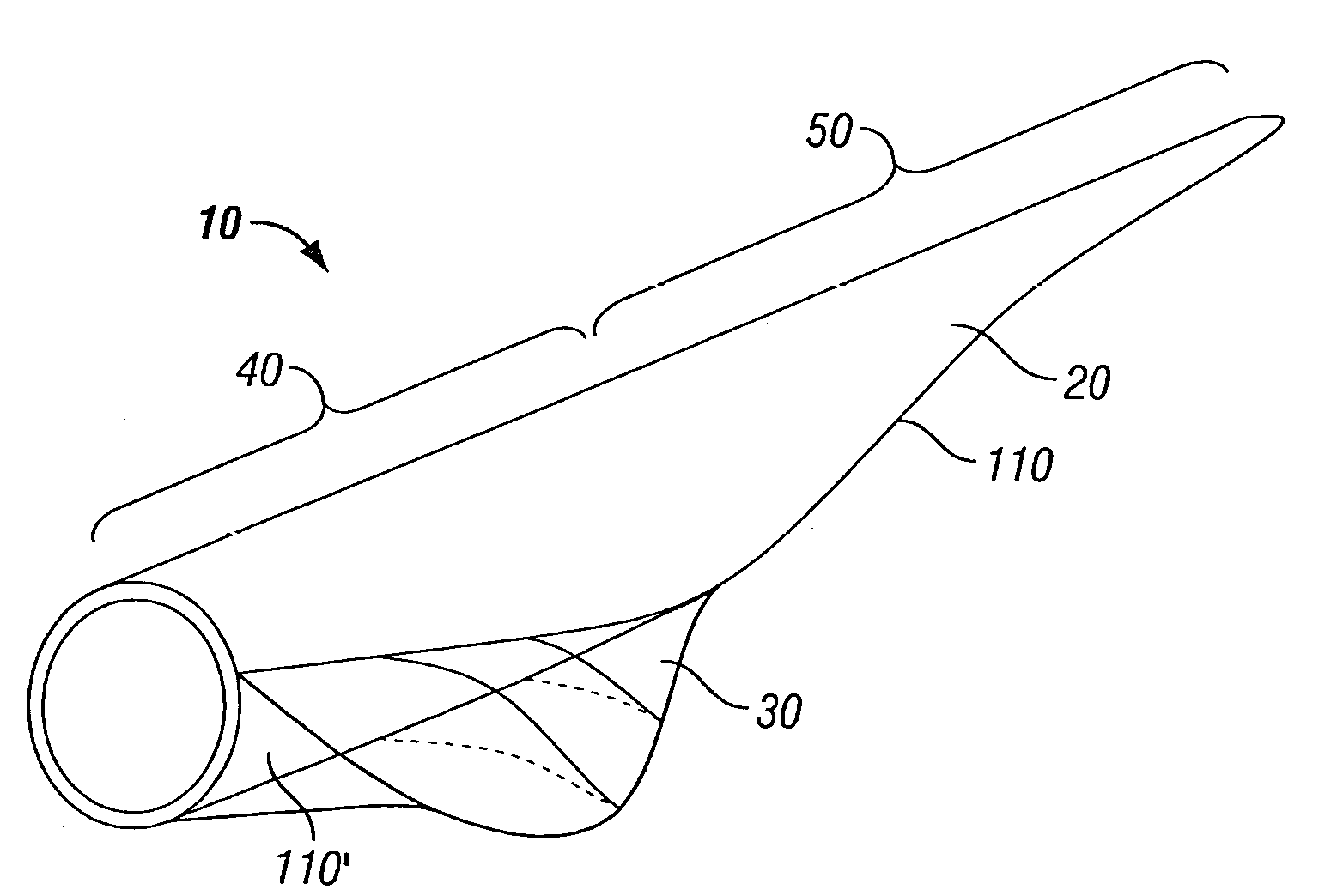
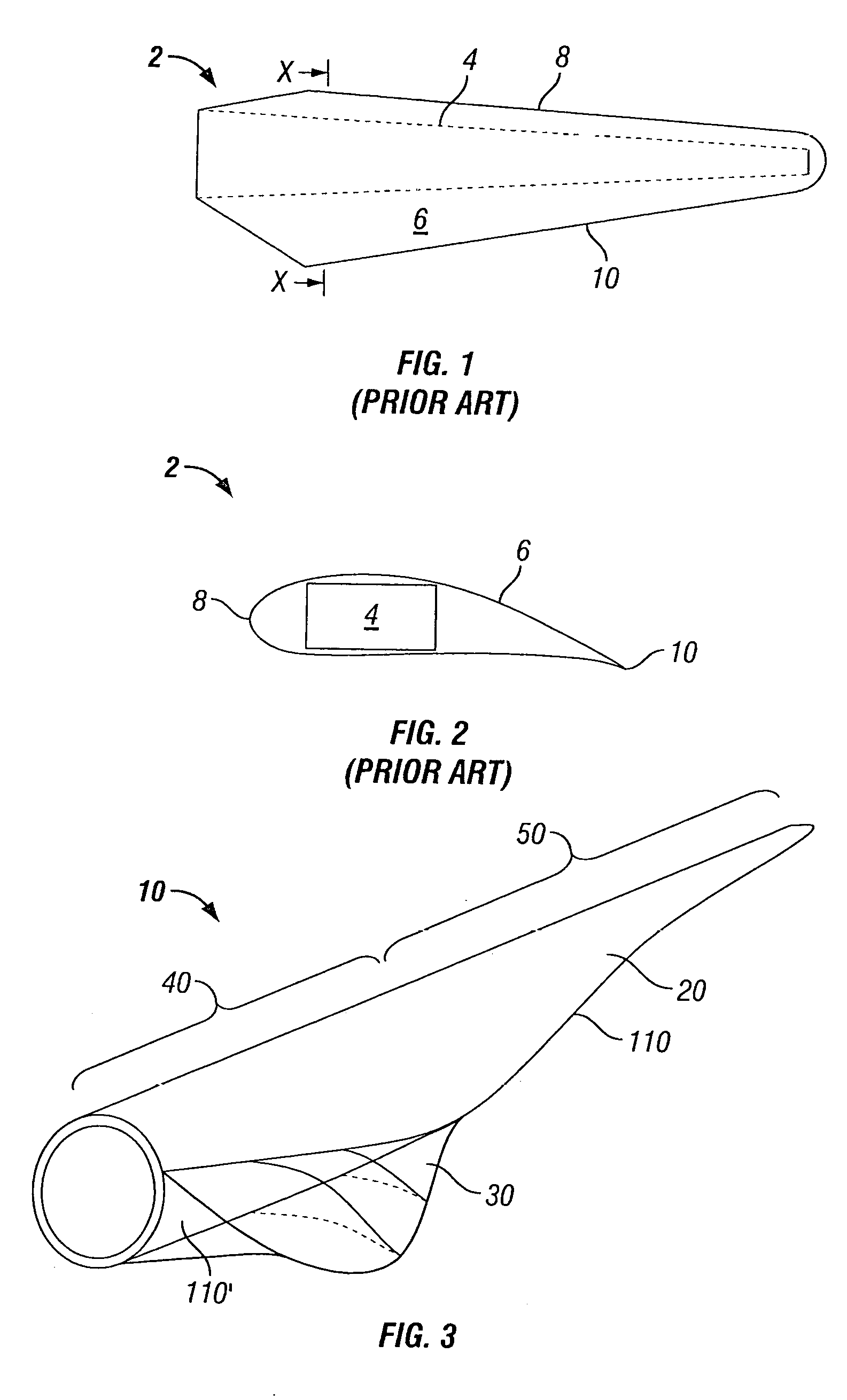
[0056]FIG. 3 illustrates a rotor blade 10 comprising a blade portion 20 and an extension portion 30. A proximal or “root” end 40 of the blade portion 20 is configured to be connected to a rotor hub of a wind turbine installation (not shown), while the distal end 50 of the blade portion 20 extends from the root end 40, and is supported thereby in a cantilevered manner. This distal end 50 represents a “tip” of the blade 10. The length of a rotor blade 10 may be in the range of 20 to 150 metres in length but is typically in the range of 20 to 70 metres. An extension portion 30 is appended to a rearmost region of the root end 40. In the illustrated embodiment the extension portion 30 is appended at an extreme proximal location, adjacent to where the rotor blade is connected to the rotor hub in use, however, the extension portion 30 may be spaced from this extreme proximal location towards the tip of the blade.

[0057]A schematic representing a cross section of the root end 40 of the rotor...


PUM


Abstract

A wind turbine rotor blade extension portion having a permanent framework with one or more chord-wise members and a substantially span-wise member. A membrane is located over the framework to thereby generate a streamlined surface. The extension portion is configured to transmit aerodynamic loads from the membrane, along the chord-wise members to a rotor blade to which the extension portion is connected, in use.

Description

BACKGROUND OF THE INVENTION[0001]1. Field of the Invention[0002]The present invention relates to the field of rotor blades for wind turbine installations. In particular, it relates to means for extending a chord-wise dimension of a portion of said rotor blades.[0003]2. Description of the Related Art[0004]Wind turbine installations are continuously being developed to enable the installation to capture and subsequently convert an increasing amount of the energy represented by the wind into electricity. In particular, it is desirable to increase the surface area of the blade that is presented to the wind to enable a more efficient capture of said energy. However, in providing a rotor blade having an increased surface area, increased loading is experienced by the structure of the blade.[0005]Blade design involves optimisation of a number of characteristics of the blade. This optimisation typically involves selection of the aerofoil section to be used and variation of the aerofoil sectio...

Claims


Application Information

Patent Timeline
IPC IPC(8): F03D11/00
CPCF05B2230/60F03D1/0641F03D1/065F03D1/0675F05B2260/301Y02E10/721F05B2240/301F05B2230/80Y02E10/72Y02P70/50F03D1/06F03D1/0608
Inventor VRONSKY, TOMASHANCOCK, MARK
Owner VESTAS WIND SYST AS
Why Eureka
Try Eureka