

Power plant
- Summary
- Abstract
- Description
- Claims
- Application Information
AI Technical Summary
Benefits of technology
Problems solved by technology
Method used
Image

Examples
first embodiment
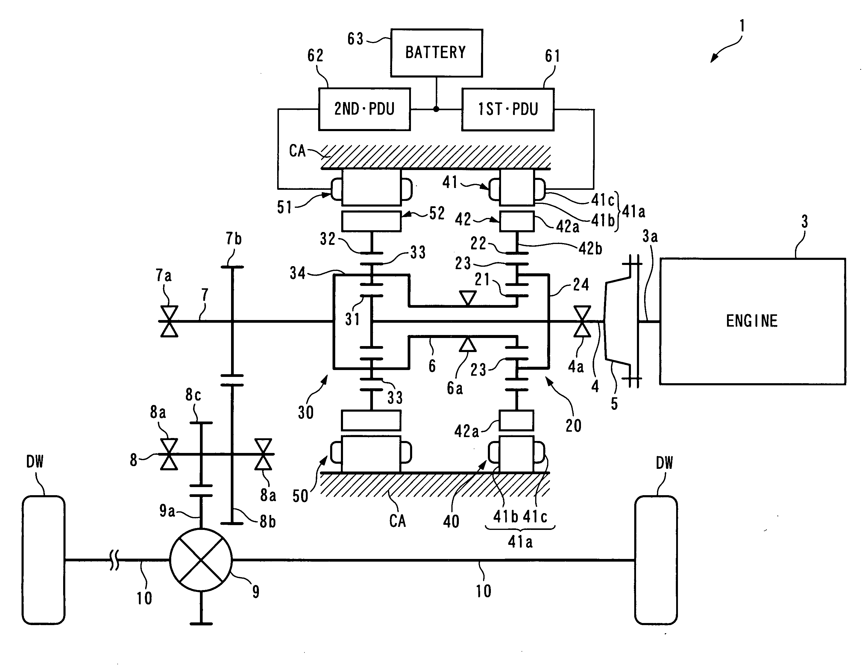
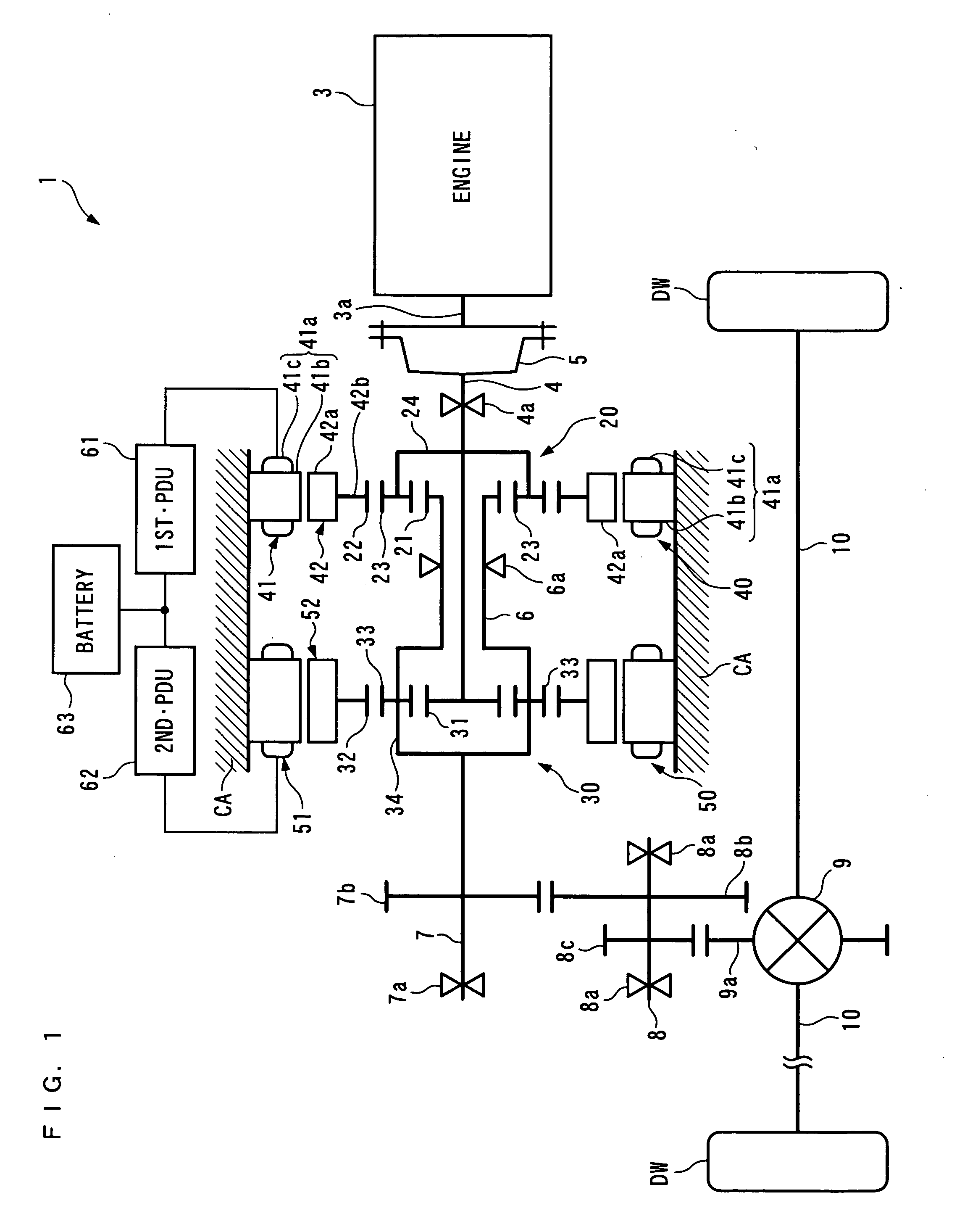
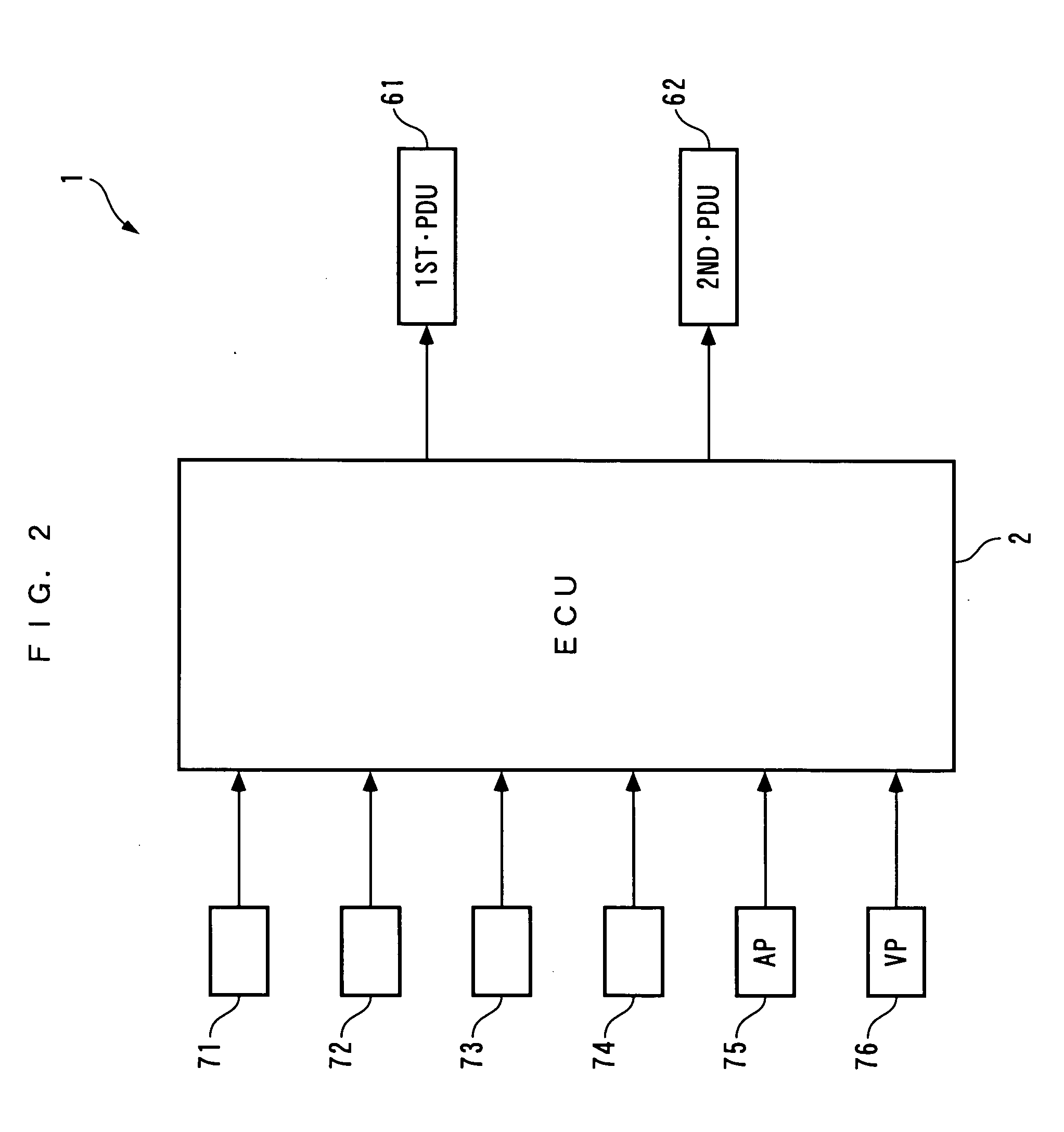
[0217]The present invention will now be described in detail with reference to the drawings showing a preferred embodiment thereof. It should be noted that in the figures, hatching for portions illustrating cross-sections are omitted for convenience. FIGS. 1 and 2 schematically show a power plant 1 according to the present embodiment. The power plant 1 is for driving left and right drive wheels DW and DW (driven parts) of a vehicle (not shown), and as shown in FIG. 1, includes an internal combustion engine 3 (prime mover), a first generator-motor 40 and a second generator-motor 50 as power sources, and a first planetary gear unit 20, a second planetary gear unit 30 and a differential gear mechanism 9 for transmitting power to the drive wheels DW and DW. Further, as shown in FIG. 2, the power plant 1 includes an ECU 2, a 1st·PDU 61 and a 2nd·PDU 62, for controlling the operations of the internal combustion engine 3 and the first and second generator-motors 40 and 50, respectively.
[021...
second embodiment
[0350]Further, in the second embodiment, the connecting relationship between the engine 3, the drive wheels DW and DW, the stepless transmission 110, the first and second sun gears 21 and 31, the first and second carriers 24 and 34, and the first and second ring gears 22 and 32 can be set as desired insofar as they satisfy the following conditions: One of the first sun gear 21 and the first ring gear 22, and the second carrier 34 are connected to the drive wheels DW and DW; one of the second sun gear 31 and the second ring gear 32, and the first carrier 24 are connected to the engine 3; and the other of the first sun gear 21 and the first ring gear 22 and the other of the second sun gear 31 and the second ring gear 32 are connected to the stepless transmission 110.
[0351]For example, the first carrier 24 and the second ring gear 32 may be connected to the engine 3, the first ring gear 22 and the second carrier 34 to the drive wheels DW and DW, and the first and second sun gears 21 an...
fourth embodiment
[0506]Further, also in the present embodiment, as described above with reference to FIG. 59, if the third and second generator-motors 220 and 50 are used, it is possible to transmit the engine power WENG to the drive wheels DW and DW while steplessly changing the speed thereof, thereby making it possible to reduce the frequency of the speed-changing operation of the transmission 240. This makes it possible to suppress heat losses by the speed-changing operation, whereby it is possible to ensure the high driving efficiency of the power plant 1D. In addition to this, according to the present embodiment, it is possible to obtain the same advantageous effects as provided by the
[0507]It should be noted that although in the present embodiment, the transmission 240 is a belt-type stepless transmission, it is to be understood that a toroidal-type or a hydraulic-type stepless transmission or a gear-type stepped transmission may be employed.
PUM
 Abstract
Description
Claims
Application Information