Multi-ply fibrous structures and processes for making same

a fibrous structure and multi-ply technology, applied in the field of multi-ply structure, can solve the problems of large patterned roll fabrication complexity and variation in embossing clarity, inadequate plybonding, and relatively high emboss area that needs to be bonded

Inactive Publication Date: 2010-02-04
THE PROCTER & GAMBLE COMPANY
View PDF60 Cites 29 Cited by
  • Summary
  • Abstract
  • Description
  • Claims
  • Application Information

AI Technical Summary

Benefits of technology

[0016]b. applying a compressive force to the multi-ply fibrous structure that exhibits a plybond strength of greater than 0.5 g / in, is provided.
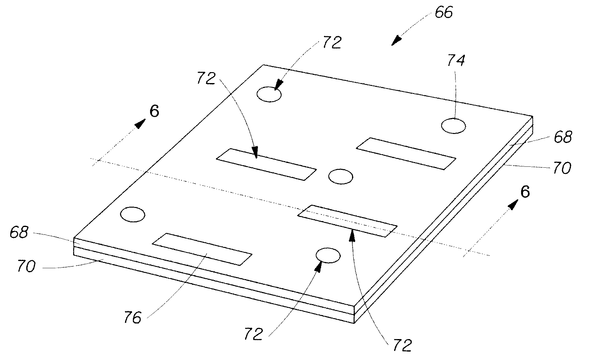
[0017]In still another example of the present invention, an adhesive application system comprising a permeable roll comprising an interior volume comprising an adhesive, wherein the interior volume is in fluid communication via a plurality of holes with an external environment comprising a fibrous structure comprising embossments, wherein the holes are arranged such that the adhesive is applied to less than the entire area of embossments, is provided.

Problems solved by technology

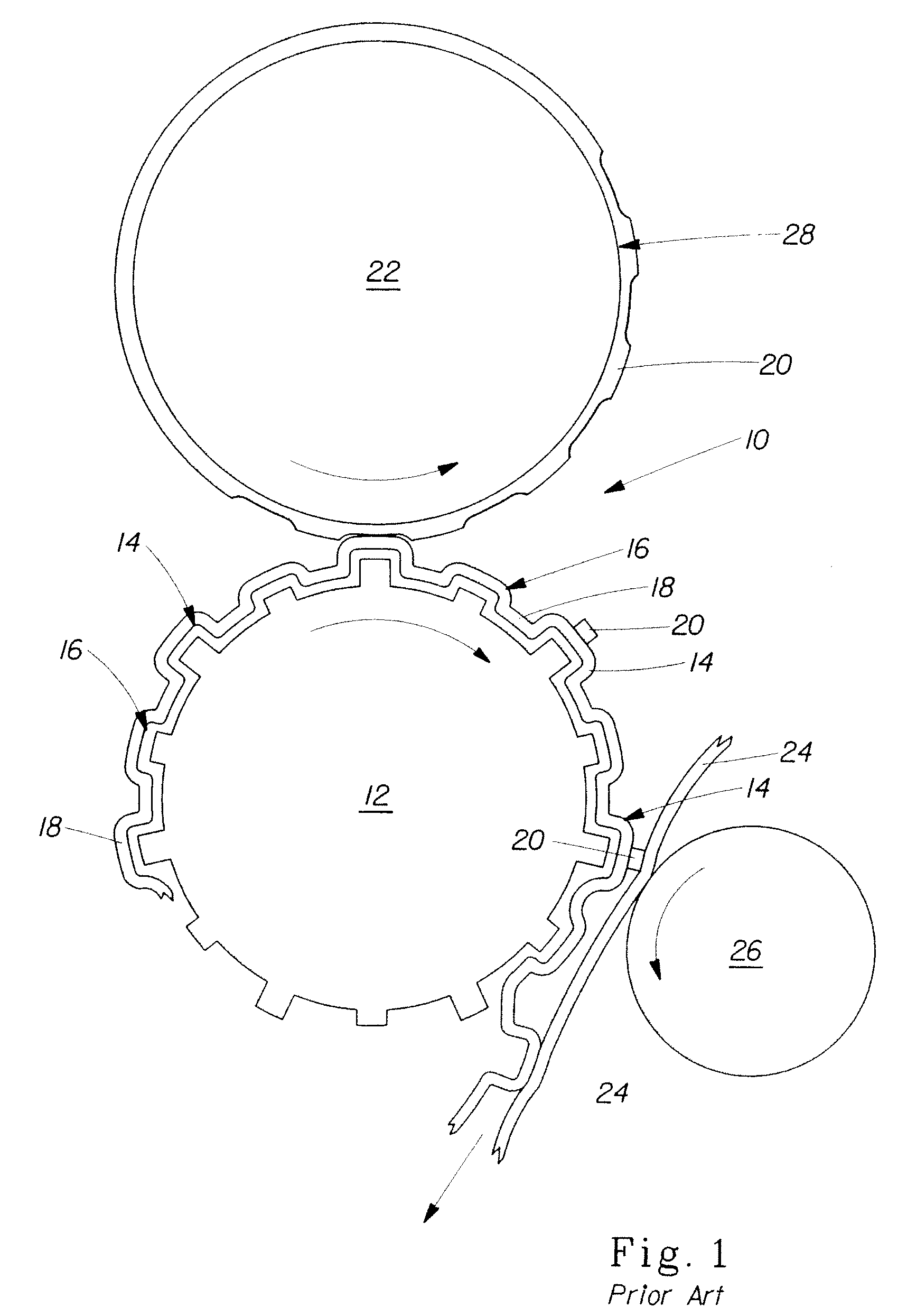
This approach has significant limitations including patterned roll fabrication complexity and variation in embossment clarity (the higher embossment elements 14 are typically exposed to higher pressure than the lower embossment elements 16, such as in a rubber-steel emboss nip).
Limitations of this approach are hygiene issues on the patterned applicator roll (glue, dust, and paper build up in the relieved areas) and inadequate plybond if sufficient emboss area is not bonded (the portion of the emboss area that needs to be bonded may be relatively high since the amount of adhesive carried on the surface of the patterned applicator roll is typically relatively low).
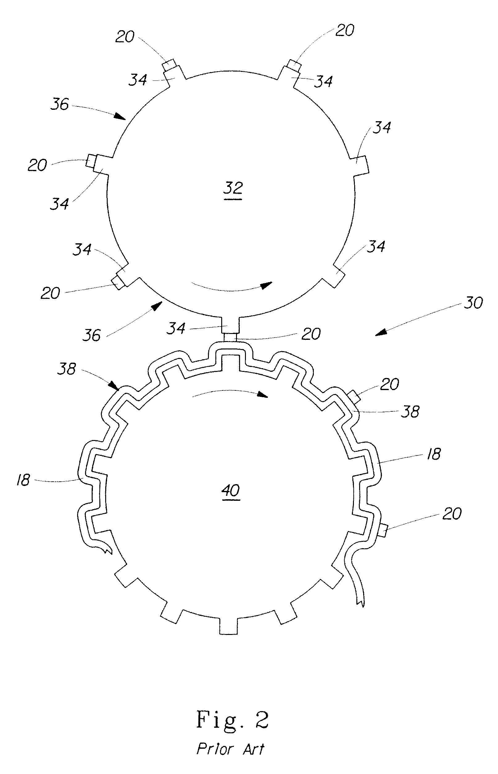
Limitations with this approach include poor emboss appearance retention (since very little of the emboss area is bonded), flattened emboss appearance if the sheets are laminated in a calendar, and inefficient / costly adhesive utilization in nested and knob-knob configurations (since most of the glue will not correspond to emboss areas and will therefore not be exposed to laminating pressure, and therefore will not result in effective bonding).
Limitations of this approach are hygiene issues on the patterned marrying roll 50 (glue, dust, and paper build up in the relieved areas) and inadequate plybond if sufficient emboss area is not bonded (the portion of the emboss area that needs to be bonded may be relatively high since the amount of adhesive carried on the surface of the applicator roll is typically relatively low), and inefficient / costly adhesive utilization (since most of the glue will not correspond to emboss areas and will therefore not be exposed to laminating pressure, and therefore will not result in effective bonding).

Method used


Image

  • Multi-ply fibrous structures and processes for making same
  • Multi-ply fibrous structures and processes for making same
  • Multi-ply fibrous structures and processes for making same

Examples


Embodiment Construction

Definitions

[0027]“Fibrous structure” as used herein means a structure that comprises one or more filaments and / or fibers. In one example, a fibrous structure according to the present invention means an orderly arrangement of filaments and / or fibers within a structure in order to perform a function. Nonlimiting examples of fibrous structures of the present invention include paper, fabrics (including woven, knitted, and non-woven), and absorbent pads (for example for diapers or feminine hygiene products).

[0028]Nonlimiting examples of processes for making fibrous structures include known wet-laid papermaking processes and air-laid papermaking processes. Such processes typically include steps of preparing a fiber composition in the form of a suspension in a medium, either wet, more specifically aqueous medium, or dry, more specifically gaseous, i.e. with air as medium. The aqueous medium used for wet-laid processes is oftentimes referred to as a fiber slurry. The fibrous slurry is then ...


PUM

PropertyMeasurementUnit
viscosityaaaaaaaaaa
viscosityaaaaaaaaaa
viscosityaaaaaaaaaa

Abstract

Multi-ply fibrous structures, more particularly to embossed multi-ply fibrous structures and processes for making same are provided.

Description

FIELD OF THE INVENTION[0001]The present invention relates to multi-ply fibrous structures, more particularly to embossed multi-ply fibrous structures and processes for making same.BACKGROUND OF THE INVENTION[0002]Multi-ply fibrous structures wherein two or more fibrous structure plies are adhesively bonded together (“plybonded”) are known in the art. Examples of known plybonding techniques, especially partial plybonding techniques for embossed multi-ply fibrous structures are described below.[0003]As shown in FIG. 1, in one prior art plybonding technique 10, an embossing patterned roll 12 may be made with some emboss elements at a greater radial distance from the roll center than other emboss elements thus resulting in higher embossments elements 14 and lower embossment elements 16 in an embossed fibrous structure 18. Only the higher embossment elements 14 are contacted with an adhesive 20 via a smooth applicator roll, 22. As the embossed fibrous structure 18 is combined with anothe...

Claims


Application Information

Patent Timeline
Patent Type & Authority Applications(United States)
IPC IPC(8): A61F13/15D21H27/30D21H25/04B05C1/10
CPCA61F13/15D21H25/04D21H27/30D21H27/02D21H27/004
Inventor BUSCHUR, PATRICK J.MCNEIL, KEVIN BENSON
Owner THE PROCTER & GAMBLE COMPANY
Why Eureka
Try Eureka