Prosthesis for nucleus or inter-vertebral disc replacement

a technology for intervertebral discs and prostheses, which is applied in the field of prosthesis for nucleus or intervertebral disc replacement, can solve the problems of limited space available for implant placement, substantial wear of implants, and generating surface defects at the turning axis. achieve the effect of simple us

Inactive Publication Date: 2010-02-04
SPINEWAY
View PDF6 Cites 27 Cited by
  • Summary
  • Abstract
  • Description
  • Claims
  • Application Information

AI Technical Summary

Benefits of technology

[0034]allow extremely simple use based on a minimum of two components.

Problems solved by technology

In fact, as observed previously, the space available to lodge the implant is limited.
Furthermore, it has been found that the penetration of the scar tissues into the spaces left free in the volume of the prosthesis could cause it to be blocked, and eventually its fusion in a bony massif.
Similarly, the provision of spherical articular surfaces systematically resorts to the turning technology, which has the drawback of generating a surface defect at the turning axis.
This defect is generally located at the centre of the articular surface and can therefore cause substantial wear of the implant.
The solutions proposed by the prior art are unable to meet all of these various requirements.
This space cannot be filled by the core because the radii of the articular surfaces, which are necessarily lower than the height of the implant, limit its diameter in a plane perpendicular to its axis.
Thus, it needlessly increases the height of the implant.
Moreover, the radius of curvature of the articular surfaces is necessarily very short, to allow suitable displacement, thereby freeing a large peripheral space, which is favourable to bone fusion, and therefore contrary to the desired result.
This configuration needlessly increases the height of the implant.
Moreover, as it is presented, the implant does not comply with the anatomical centre of rotation, and further comprises peripheral spaces which are favourable to bone fusion.

Method used


Image

  • Prosthesis for nucleus or inter-vertebral disc replacement
  • Prosthesis for nucleus or inter-vertebral disc replacement
  • Prosthesis for nucleus or inter-vertebral disc replacement

Examples


Embodiment Construction

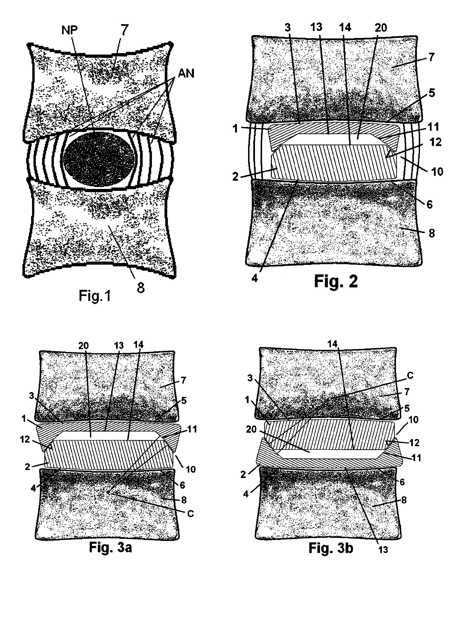
[0051]FIG. 1 shows a healthy natural disc between two vertebrae (7) and (8), comprising its nucleus pulposus (NP) and its annulus (AN).

[0052]FIG. 2 shows a nucleus replacement implant according to the invention. Its size is reduced with regard to a complete prosthesis, in order to preserve part of the annulus.

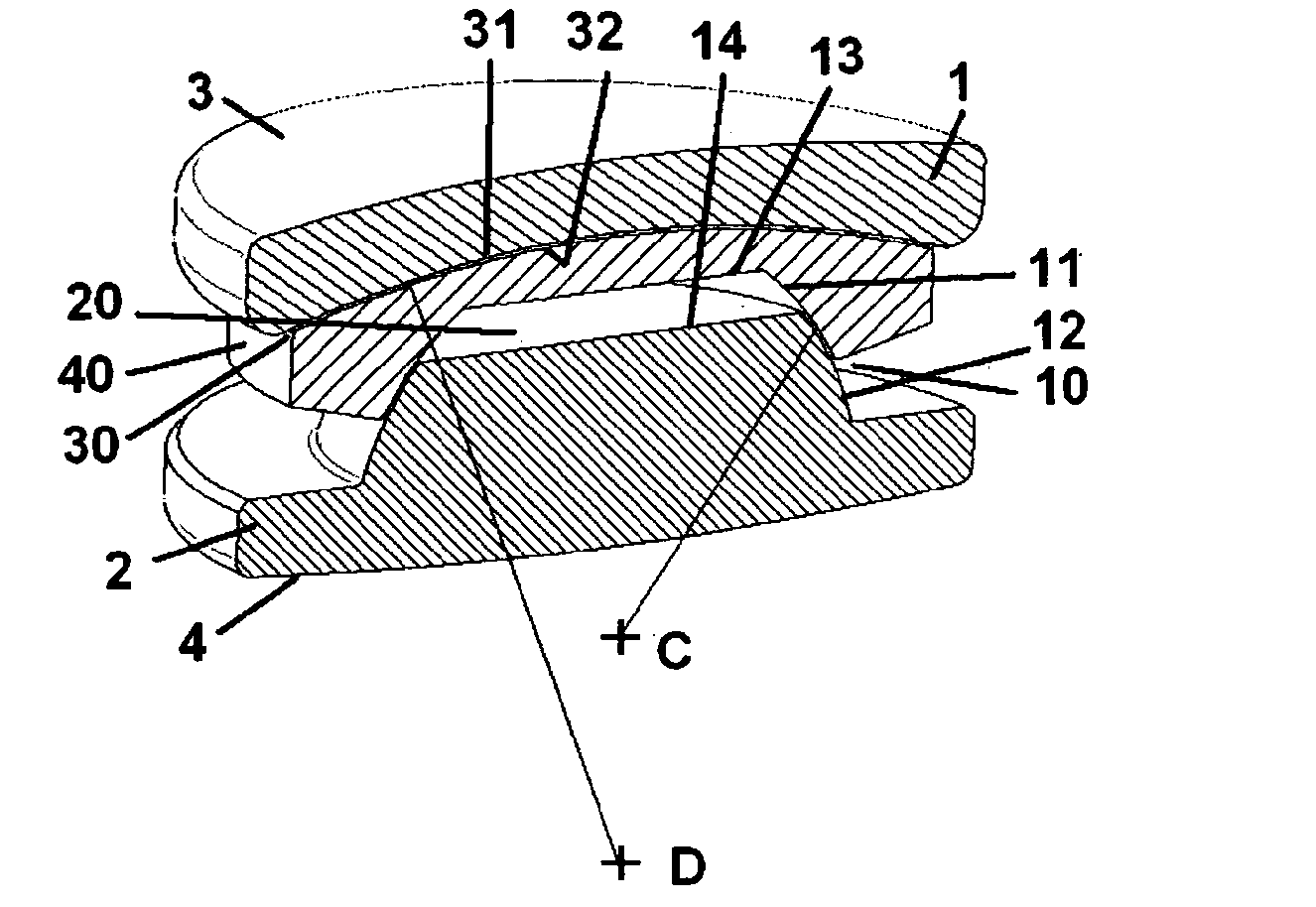
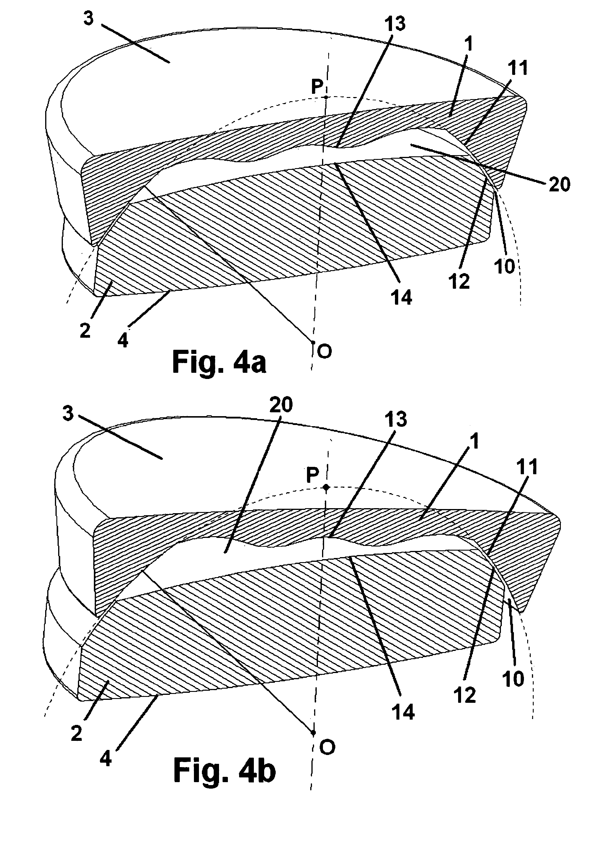
[0053]FIG. 3a shows a complete disc prosthesis according to the invention, in place between the vertebrae (7) and (8). In this particular embodiment, the surfaces that intersect the articular surfaces are planar and approximately located in the neighbourhood of the pole of the articulation, and the instantaneous centre of rotation (C) is located below the inter-vertebral space.

[0054]FIG. 3b shows a complete disc prosthesis according to the invention, virtually identical to that of FIG. 3a, but for which it was decided to position the instantaneous centre of rotation (C) above the inter-vertebral space. This configuration does not comply with the anatomical centre of rotation an...


PUM

PropertyMeasurementUnit
curvature radiiaaaaaaaaaa
volumeaaaaaaaaaa
radiiaaaaaaaaaa

Abstract

The invention relates to a nucleus or inter-vertebral disc prosthesis that comprises at least two plates capable of movement relative to each other through at least one articulation interface defined by a female surface and a male surface each having an essentially spherical shape and essentially equal diameters. The two articulation surfaces are respectively intersected by surfaces that define between them a relative mobility space for the plates when the articulation surfaces are coapted; the surface intersecting the female surface being contained in the volume defined by an equatorial plane of said sphere except for said equatorial plane itself, the surface intersecting the male surface being planar or convex.

Description

FIELD OF THE INVENTION[0001]The present invention relates to a prosthesis for completely replacing a damaged inter-vertebral disc of the human vertebral column, or for partially replacing it, by substituting only for its “nucleus pulposus”. Its field of application is therefore orthopaedic surgery.[0002]In the vertebral column, each vertebra is separated from the adjacent vertebrae by a fibro-cartilaginous disc, called inter-vertebral disc. These discs have a support, articulation and damping role between each vertebra.[0003]The degeneration of these discs harms their functions and can cause pain or disabling functional limitations.[0004]One of the techniques used to treat patients suffering from such disorders is to resort to surgery to replace the complete degenerative disc, or only its “nucleus pulposus”, by a prosthesis restoring the functions of the excised organ as closely as possible.PRIOR ART[0005]Various articular prostheses for inter-vertebral discs have been proposed to d...

Claims


Application Information

Patent Timeline
Patent Type & Authority Applications(United States)
IPC IPC(8): A61F2/44
CPCA61F2/44A61F2310/00407A61F2002/30362A61F2002/30364A61F2002/30369A61F2002/30387A61F2002/30563A61F2002/3065A61F2002/30654A61F2002/30662A61F2002/30663A61F2002/30841A61F2002/443A61F2002/444A61F2220/0025A61F2220/0033A61F2310/00029A61F2/4425
Inventor SIMON, LIONEL
Owner SPINEWAY
Why Eureka
Try Eureka