Vehicle air conditioning system

a vehicle air conditioning and air conditioning system technology, applied in the field can solve the problems of ineffective conventional operation of vehicle air conditioning systems, waste of energy cooling the evaporator, and too cold to send directly into the passenger compartment, so as to reduce the thermal load of an air conditioning system

Inactive Publication Date: 2010-02-11
NISSAN MOTOR CO LTD
View PDF3 Cites 28 Cited by
  • Summary
  • Abstract
  • Description
  • Claims
  • Application Information

AI Technical Summary

Benefits of technology

[0010]One object of the present invention is to redu

Problems solved by technology

Air passing through the evaporator is cooled but is too cold to send directly into the passenger compartment.
This conventional way of operating the vehicle air conditioning system is inherently inefficient.
Energy is wasted by cooling the evaporator to a temperature just above the freezing point of water regardless of the cooling requirements.
Further, the re-heating of cooled air represents an additional waste of ene

Method used


Image

  • Vehicle air conditioning system
  • Vehicle air conditioning system
  • Vehicle air conditioning system

Examples


first embodiment

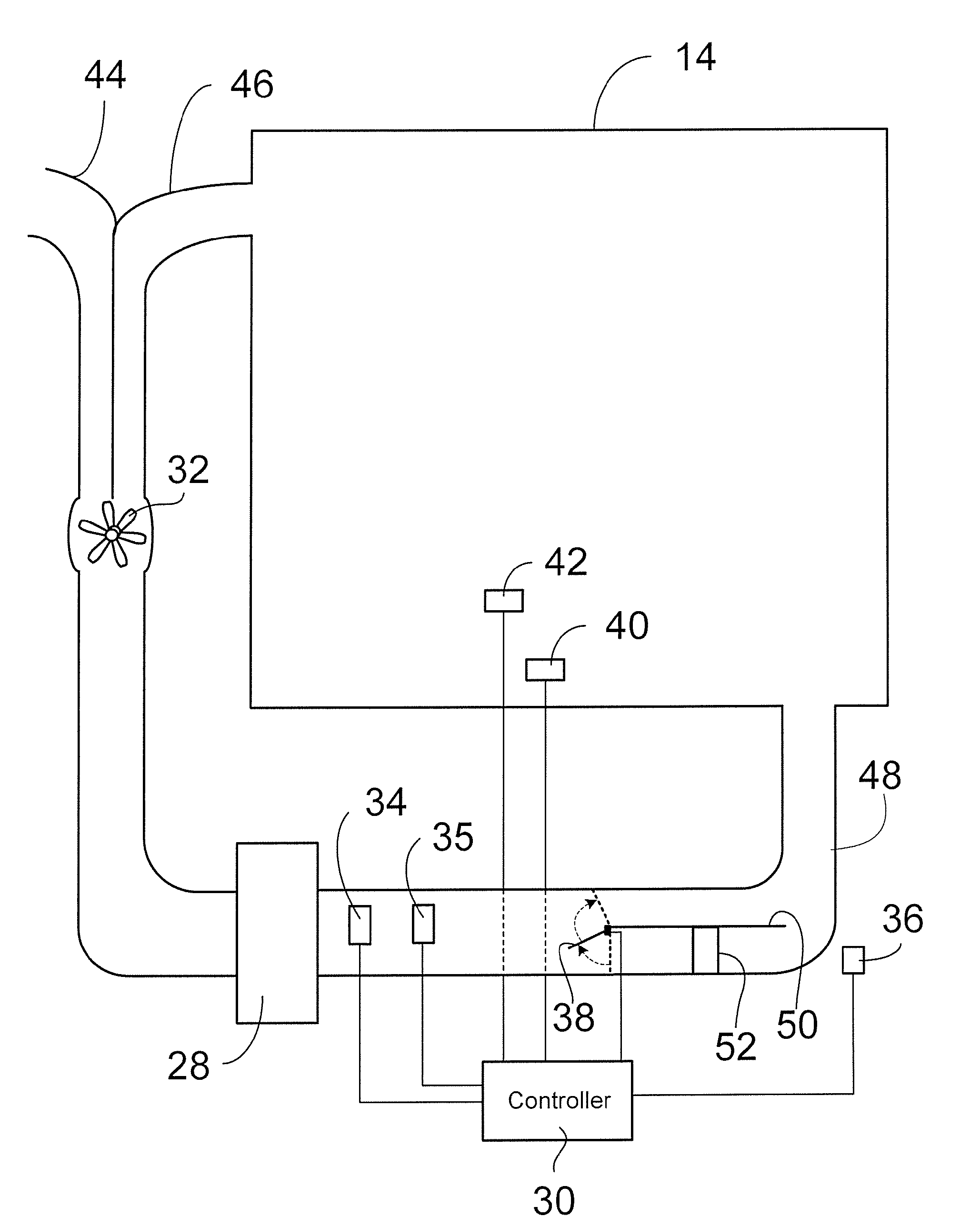
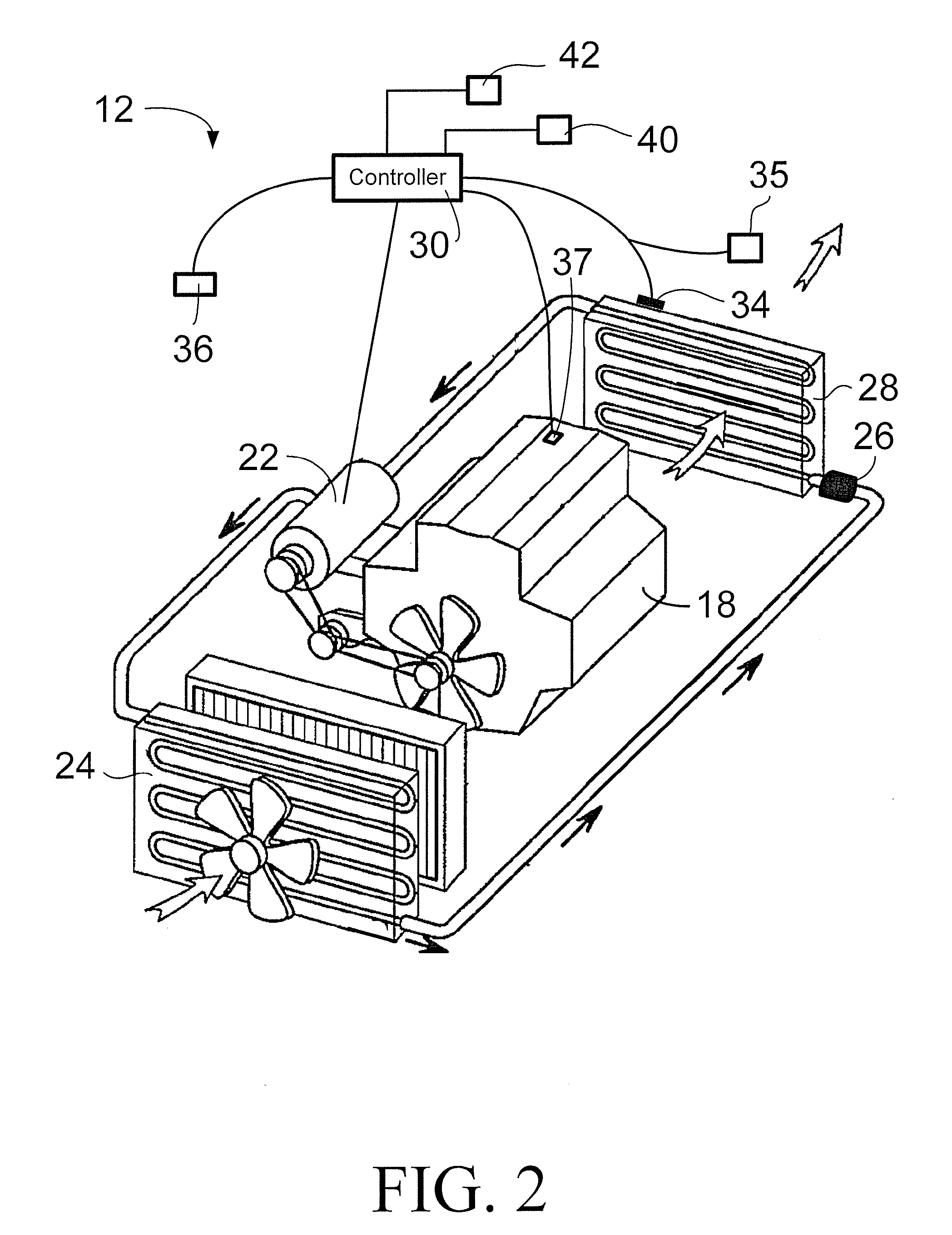
[0067]Referring now to FIGS. 4 and 5, operational steps in accordance with a first embodiment of the present invention will now be explained. In the first embodiment, the controller 30 is programmed or includes circuitry that enables operation of the compressor 22 including the basic steps described below. It should be understood from the drawings and the description below, that the depiction in FIG. 4 shows basic operational steps that can be implemented in a variety of ways. The first embodiment is one example of operation of the air conditioning system 12 by the controller 30.

[0068]At step S1, the air conditioning system 12 is switched on along with the blower 32 and initially, the air conditioning system 12 operates in the basic cooling mode with predetermined temperature cycling limits. The controller 30 determines the requested outlet temperature RO. If the requested outlet temperature RO does not exceed the compressor-on temperature, the controller 30 continues to engage the ...

second embodiment

[0080]Referring now to FIGS. 6, 7 and 8, operational steps in accordance with a second embodiment of the present invention will now be explained. In the second embodiment, the controller 30 is programmed or includes circuitry that enables operation of the compressor 22 including the basic steps described below. The second embodiment is another example of operation of the air conditioning system 12 by the controller 30 in accordance with the present invention.

[0081]In the second embodiment, the controller 30 operates the compressor 22 in a basic cooling mode, a transition mode and a reduced load mode, as described in greater detail below. In the second embodiment, the controller 30 is also programmed to control the positioning of the air flow control door 38.

[0082]As described above with respect to the first embodiment, in the basic cooling mode, the controller 30 typically cycles the compressor 22 on and off in order to remove heat as smoothly and rapidly as possible from air enteri...


PUM


Abstract

A vehicle air conditioning system includes a compressor, a condenser, an evaporator, a humidity sensor and a controller. The compressor is configured to compress refrigerant and the condenser is fluidly coupled to the compressor to receive the refrigerant from the compressor. The evaporator is fluidly coupled to the condenser to receive the refrigerant from the condenser and fluidly coupled to the compressor to supply the refrigerant to the compressor. The humidity sensor is positioned proximate the evaporator to detect moisture density of air passing through the evaporator towards a vehicle passenger compartment. The controller is operatively coupled to the humidity sensor and the compressor to cycle the compressor on and off to maintain the moisture density in the air being cooled by the evaporator and sensed by the humidity sensor below a predetermined moisture density threshold.

Description

BACKGROUND OF THE INVENTION[0001]1. Field of the Invention[0002]The present invention relates to a vehicle air conditioning system that controls compressor cycling in order to reduce engine workload. More specifically, the present invention relates to a vehicle air conditioning system that controls compressor cycling in response to humidity conditions at the air conditioning system evaporator.[0003]2. Background Information[0004]Vehicle air conditioning systems typically maintain the temperature of the passenger compartment by operating a compressor to keep the evaporator at a temperature just above the freezing point of water. Air passing through the evaporator is cooled but is too cold to send directly into the passenger compartment. In recent model vehicles, a portion of the cooled air is re-heated by passing the portion of the cooled air through the heater core. The cold air and the re-heated air are mixed together prior to entering the passenger compartment in order to deliver ...

Claims


Application Information

Patent Timeline
IPC IPC(8): B60H1/32F25B1/00
CPCB60H1/3207B60H2001/327B60H2001/3245
Inventor EISENHOUR, RONALD S.SPRUNGER, CHARLES
Owner NISSAN MOTOR CO LTD
Why Eureka
Try Eureka