Flow control adapter for performing spirometry and pulmonary function testing

a technology of spirometry and pulmonary function testing, applied in the field of flow control adapters for performing respiratory therapy, can solve the problems of inability to use most effective respiratory therapy for tracheostomized patients, unsuitable incentive spirometers, and inability to assess the health of patients' lungs, so as to increase the transpulmonary pressure and increase the inspiratory volume. , the effect of evaluating the health of the patient's lungs

Inactive Publication Date: 2010-02-11
SURGE INGENUITY
View PDF18 Cites 19 Cited by
  • Summary
  • Abstract
  • Description
  • Claims
  • Application Information

AI Technical Summary

Benefits of technology

[0016]In some embodiments, a method comprises providing a breathing circuit including an incentive spirometer, a flow control device, and a pulmonary testing device. Incentive spirometry testing can be performed while a patient inhales, and the flow control device inhibits inspiratory air flow towards the pulmonary testing device. In certain embodiments, the flow control device substantially prevents inspiratory air flow towards the pulmonary testing device. The pulmonary testing device is used to perform pulmonary tests while the patient exhales causing expiratory air flow through the flow control device towards the pulmonary testing device. In some embodiments, incentive spirometry testing can be performed to evaluate the health of the patient's lungs by mimicking natural sighing or yawning. ...

Problems solved by technology

Unfortunately, a patient being weaned from these types of positive pressure ventilation devices is often vulnerable to atelectasis and pneumonia.
However, the most effective forms of respiratory therapy are unavailable t...

Method used


Image

  • Flow control adapter for performing spirometry and pulmonary function testing
  • Flow control adapter for performing spirometry and pulmonary function testing
  • Flow control adapter for performing spirometry and pulmonary function testing

Examples


Embodiment Construction

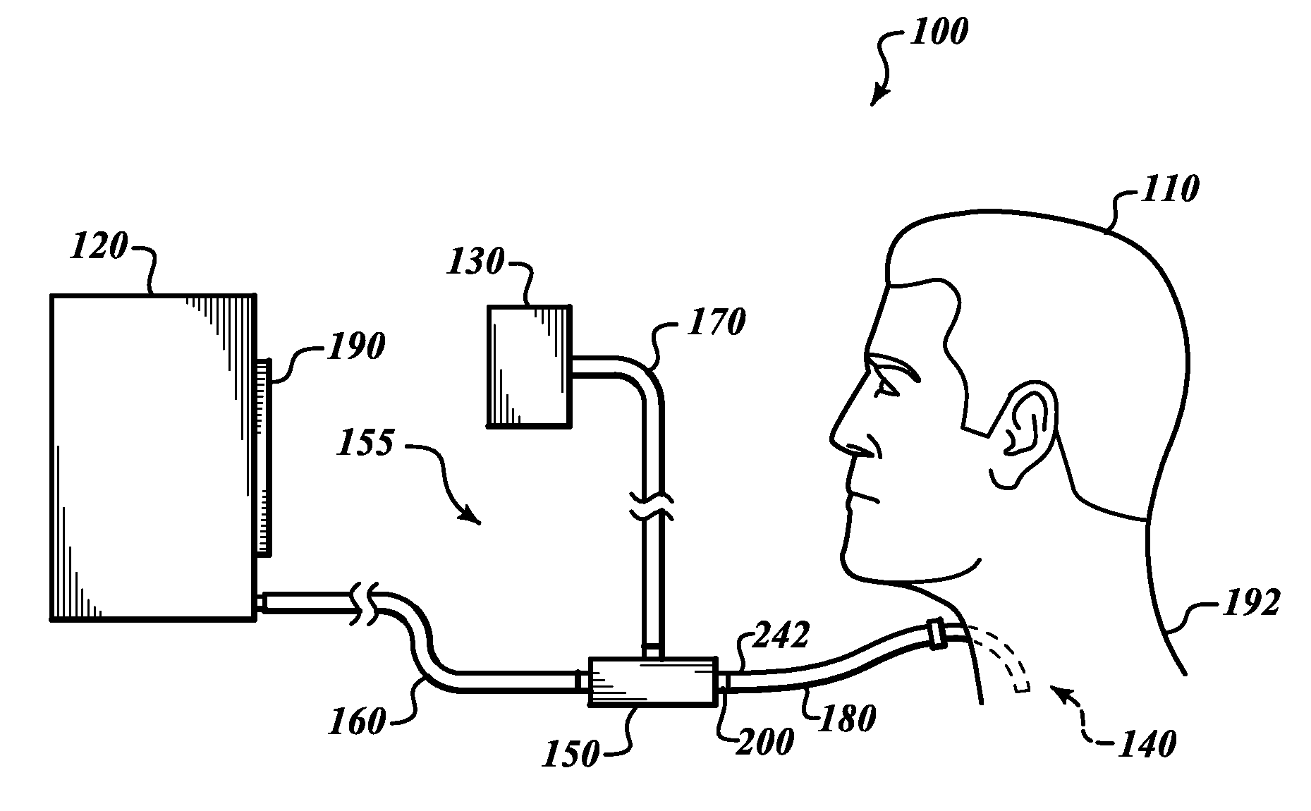
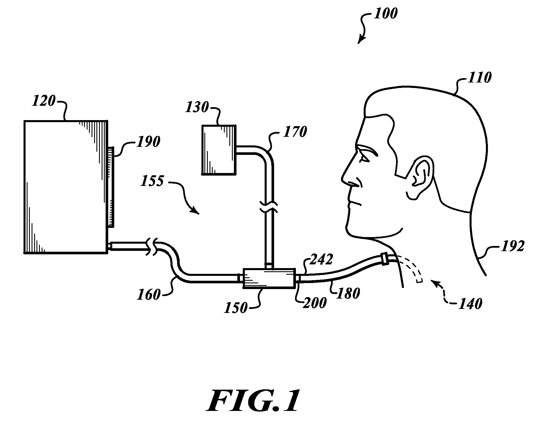
[0031]FIG. 1 shows a respiratory circuit 100 coupled to a tracheostomized subject 110. The illustrated respiratory circuit 100 can be used to perform different types of continuous or periodic spirometry (e.g., incentive spirometry), pulmonary function testing, combinations thereof, and the like. As used herein, the term “respiratory circuit” includes, without limitation, any apparatus through which a subject may breathe. A respiratory circuit may include, without limitation, one or more flow controllers, flow control adapters, spirometers, tubes (e.g., tracheostomy tubes, endotracheal tubes, and the like), fluid lines, breathing circuits, masks, mouthpieces, nebulizers, drug delivery devices, combinations thereof, or the like. As the subject 110 breathes, the respiratory circuit 100 can alternatingly perform spirometry and lung function testing. The air flow generated by the subject 110 operates the components of the circuit 100.

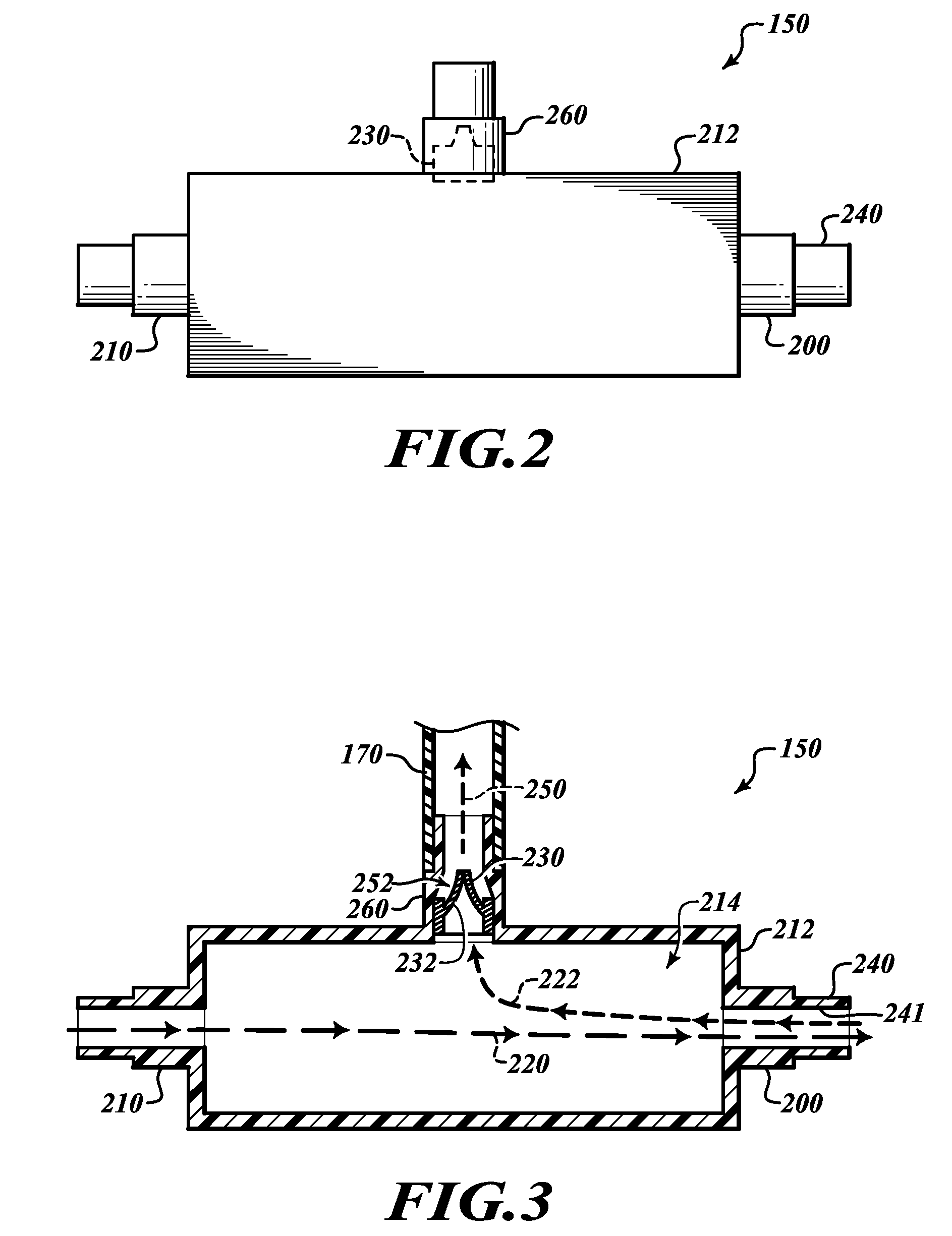
[0032]The respiratory circuit 100 generally includes a...


PUM


Abstract

A breathing circuit for a tracheostomized patient provides respiratory care and pulmonary function testing. The breathing circuit includes a flow control adapter that directs an inspiratory flow of air and an expiratory flow of air. The flow control adapter includes a subject port for coupling to a tracheostomy tube, an inspiratory port for coupling to an incentive spirometer, and an expiratory port. The flow control adapter further includes an adapter body and a one-way valve. The adapter body is configured to define an inspiratory fluid flow path between the inspiratory port and the subject port and to define an expiratory fluid flow path between the subject port and the expiratory port. The one-way valve substantially prevents air that flows generally along the inspiratory fluid flow path from flowing through the expiratory port during inspiration and allows air flowing generally along the expiratory fluid flow path to flow through the expiratory port during expiration.

Description

CROSS-REFERENCE TO RELATED APPLICATION[0001]This application claims the benefit under 35 U.S.C. §119(e) of U.S. Provisional Patent Application No. 61 / 087,893 filed Aug. 11, 2008. This provisional application is incorporated herein by reference in its entirety.BACKGROUND[0002]1. Technical Field[0003]The present invention relates generally to flow control adapters for performing respiratory therapy, and in particular, to flow control adapters for performing incentive spirometry and pulmonary function testing in tracheostomized patients.[0004]2. Description of the Related Art[0005]Tracheostomies are often performed to provide direct access to a patient's airway via an opening in the patient's neck in order to treat acute conditions or to perform an elective procedure. The acute conditions may involve maxillofacial injuries, rapidly enlarging masses (e.g., head masses, neck masses, and the like), and / or airway inflammation. The elective procedures may involve planned laryngectomies, res...

Claims


Application Information

Patent Timeline
IPC IPC(8): A61M16/04
CPCA61M16/0465A61M2205/502A61M2016/0027A61B5/091A61M2205/583A61M16/208A61M2205/3368A61B5/0873A61B5/097A61M16/0833A61M16/0816A61M16/0841A61M16/0858
Inventor TUREK, JOSEPH WILLIAMTOLOZA, ERIC MIGUEL
Owner SURGE INGENUITY
Why Eureka
Try Eureka