Hand and press-button dual-way manual pulse generator with built-in indicator lamps

a generator and indicator lamp technology, applied in the field of manual pulse generators, can solve the problems of affecting the service life of the generator, affecting the input angle, and reducing work efficiency, so as to achieve the effect of weakening the damping effect, strengthening the damping effect, and changing the damping

Active Publication Date: 2010-02-11
KEDE NUMERICAL CONTROL CO LTD
View PDF2 Cites 3 Cited by
  • Summary
  • Abstract
  • Description
  • Claims
  • Application Information

AI Technical Summary

Benefits of technology

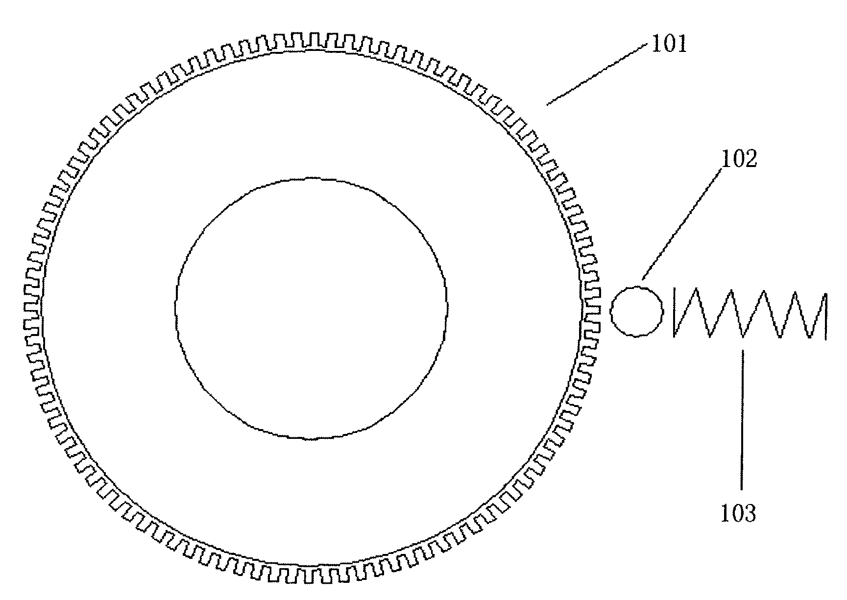
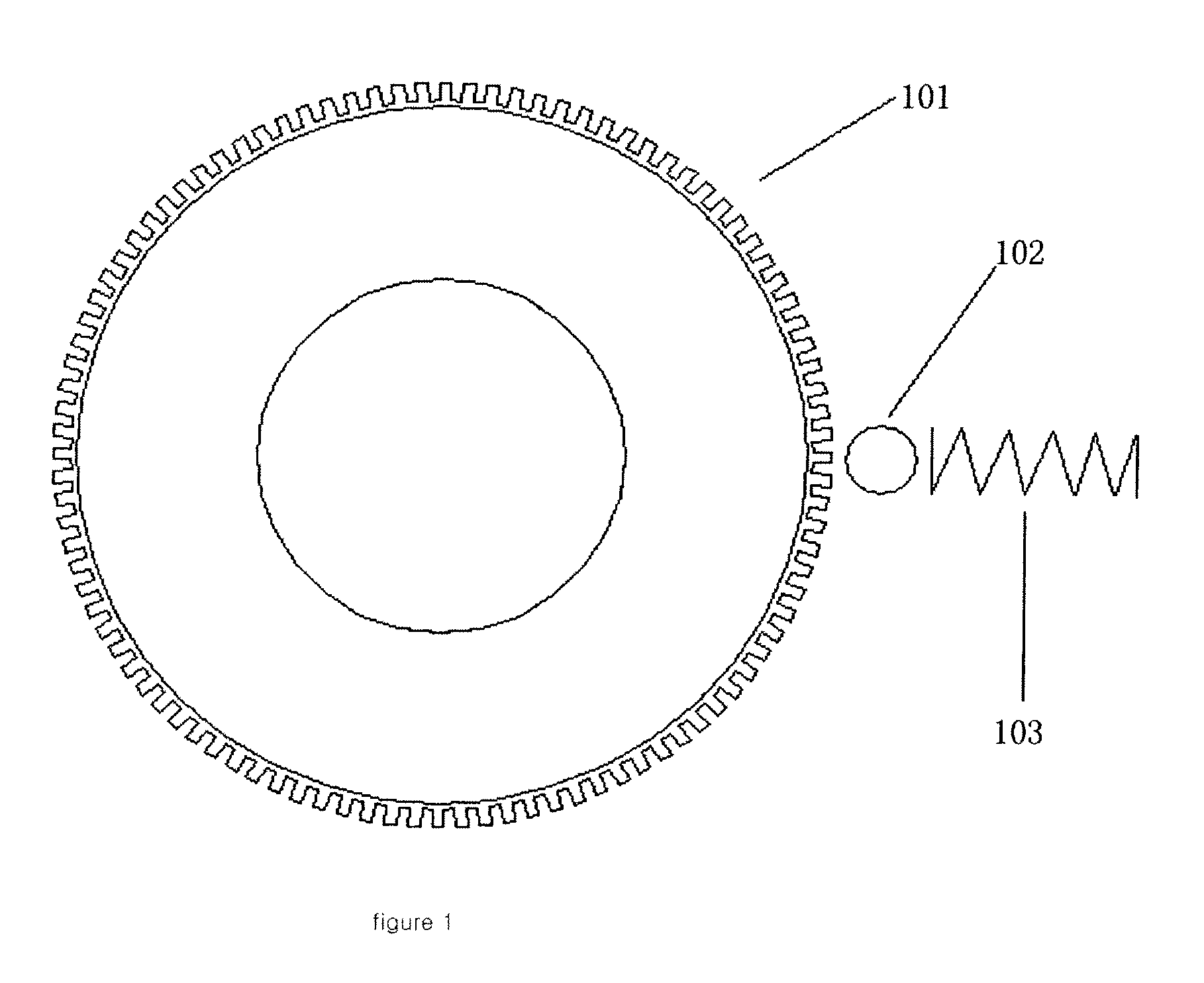
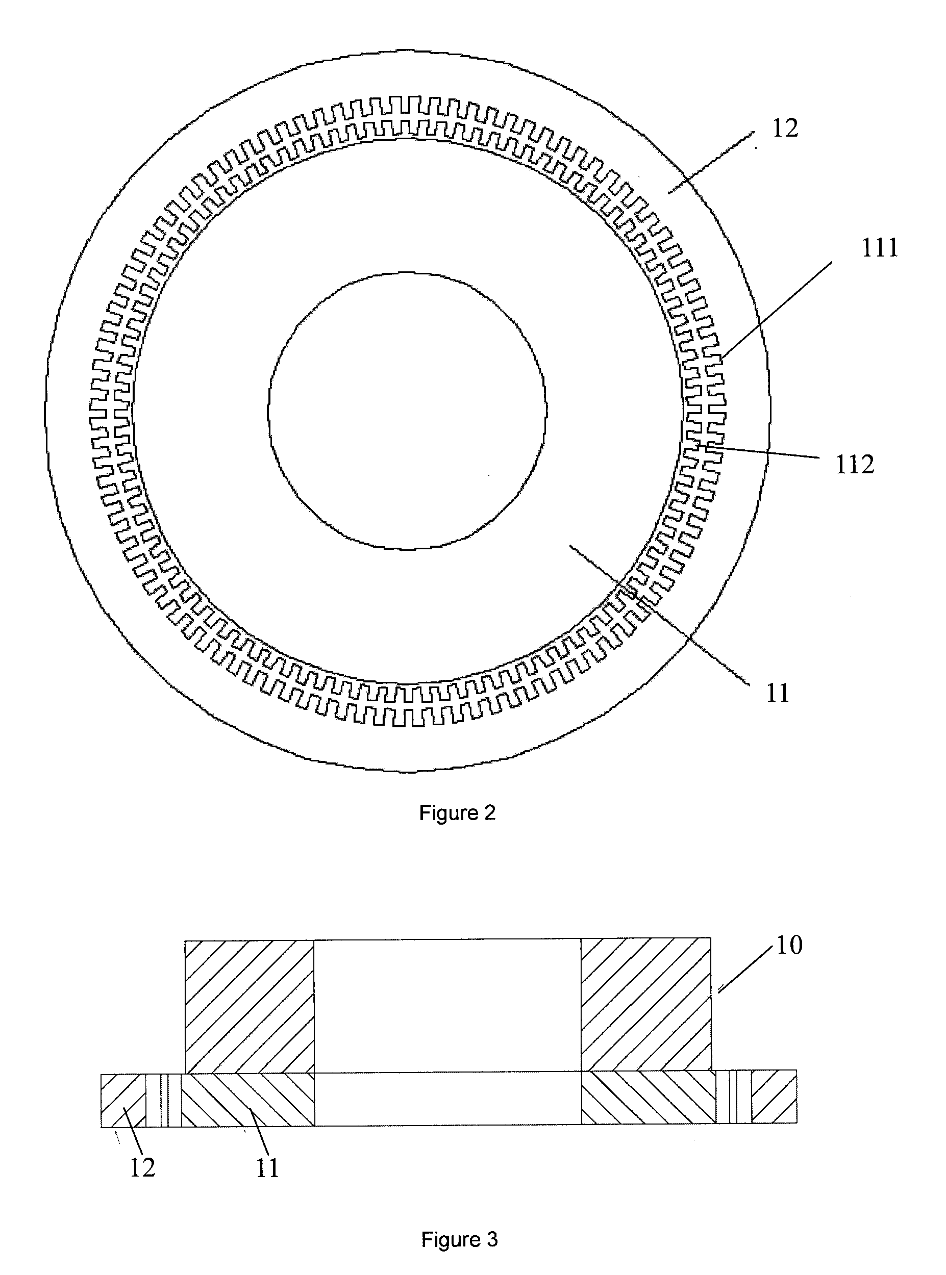
[0028]By the technical scheme, zigzag magnetic fields are formed on the outer edge of the inner ring tooth damping fins and the inner edge of the outer ring tooth damping fins, and damping action is formed through the two magnetic fields; the strength of the damping effect can be changed by adjusting the quantity of the inner ring tooth damping fins and the outer ring tooth damping fins, and the more the damping fins are, the stronger the damping effect is; and the fewer the damping fins are, the weaker the damping effect is. As a result, the magnetic damping type manual rotation input disk with teeth has the characteristics of good damping effect, easy perception and good rotation hand feeling; since a non-contact structure is adopted, compared with those of the prior art, the service life is extended greatly, and high durability is obtained.
[0029]In addition, the controller and the built-in indicator lamps are installed on the manual pulse generator for offsetting the defects of the manual pulse generator in the prior art, and the manual pulse generator has the self-check function; with the help of the built-in indicator lamps, when turning on the numerical control machine, operators can know whether the manual pulse generator is normal, so that it is easy to eliminate the system fault; by the indicating function of the built-in indicator lamps, the operators can know whether the manual pulse generator has pulse output and the number of the output pulses is consistent with the graduation which the manual pulse generator rotates, so the reliability of the manual pulse generator is enhanced. The present invention adopts two ways of rotation and press-button pressing to input pulses, under the condition that the cutter or the workpiece needs to move longer distance, the press-buttons are only needed for realizing the output of the control signals, but the traditional method that the cranking bar needs to be swung by hundreds of circles with wasting time and effort is abandoned; consequently, the swinging time is reduced greatly, misoperation is avoided, the fault incidence is reduced, and work efficiency is enhanced greatly. Owing to the easy structure, it is easy to produce; and it is suitable for popularization with low cost.

Problems solved by technology

The previous manual pulse generator has the problem that in the state of fine adjustment, the rotating shaft is under the state of free rotation without damping, users can not perceive the input angle, and therefore, the input angle is not easy to control when operators rotate the manual pulse generator.
However, the total contact mechanical structure appears, and consequently, the service life of the generator is influenced due to the abrasion.
In addition, the traditional manual pulse generators have no indication function; when rotating the manual pulse generator, operators usually can not know whether pulses are output and the number of the output pulses is consistent with the graduation which the generator rotates; in this way, misoperation is easy to cause, and more seriously, the cutter can be broken, resulting in great damage; and meanwhile, the use of the machine tool is influenced, and consequently, the work efficiency is reduced.
When the manual pulse generator of the prior art goes wrong, the generator needs to be connected with the machine tool system for check, and in this way, a problem is caused as follows: when the machine tool goes wrong and the failure occurs under the condition of the manual pulse, maintenance personnel need to check other unrelated components, and repeatedly install the manual pulse generator which goes wrong in the system for determining the problem finally, and consequently, the work efficiency of check and maintenance operation is influenced.

Method used


Image

  • Hand and press-button dual-way manual pulse generator with built-in indicator lamps
  • Hand and press-button dual-way manual pulse generator with built-in indicator lamps
  • Hand and press-button dual-way manual pulse generator with built-in indicator lamps

Examples


example embodiment 1

[0040]As shown in FIG. 2 to FIG. 5, and FIG. 7, the manual pulse generator designed in the present invention is provided with built-in indicator lamps and a self-check circuit, and mainly comprises a rotation pulse input unit and a central processing unit (CPU) 18, wherein the CPU mainly has the functions for converting pulse signals into signals for controlling a machine tool, controlling the built-in indicator lamps, and realizing self-check when turning on. The check circuit, the forward rotation indicator lamp 801 and the inverse rotation indicator lamp 802 are shown in FIG. 7. When the machine is turned on, the check circuit is used for checking whether a manual pulse generator circuit is normal; in the operation stage, the built-in indicator lamps are used for checking whether the manual pulse generator outputs a pulse and whether the output pulse is forward or inverse. The forward rotation indicator lamp is used for indicating that the manual pulse generator outputs a forward...

example embodiment 2

[0046]As shown in FIG. 2 to FIG. 4, FIG. 6 and FIG. 8, the present invention also relates to a rotation and press-button dial-way manual pulse generator which mainly comprises a rotation signal input unit, a press-button signal input unit and a central processing unit (CPU) 18, wherein the CPU 18 mainly has the functions for converting a press-button input signal into a pulse signal, converting the pulse signal into a signal for controlling the machine tool, and selecting a circuit, and the function of other kinds of auxiliary operation. When a rotation signal generation unit outputs a pulse and the press-button unit does not output a pulse, a selection circuit outputs the pulse generated by the rotation unit; when the press-button unit outputs a pulse and the rotation unit does not output a pulse, the selection circuit outputs the pulse generated by the press-button unit; when the rotation unit outputs a pulse, press-buttons are ineffective after being pressed; when the press-butto...


PUM


Abstract

The present invention discloses a hand and press-button dual-way manual pulse generator with built-in indicator lamps, which comprises a rotation pulse input unit and a CPU. The CPU is connected with a forward rotation indicator lamp and an inverse rotation indicator lamp. The rotation signal input unit and / or the press-button signal input unit transmit the output signal to the CPU. The rotation pulse input unit transmits the output signal to the CPU where the output signal is processed and the control signal is then output through the difference chip. Meanwhile, the CPU collects control signals through the feedback circuit to realize self-check when the machine is turned on. The pulse generator has a non-contact structure extending significantly its service life than the prior art, which makes it durable. In addition, by installing a controller, built-in indicator lamps, and press-button control on the manual pulse generator, it offsets the technical defects of the current manual pulse generator, reduces the fault incidence, and greatly enhances work efficiency. Besides, the manual pulse generator has a simple structure that it is easy to manufacture and to widely spread in the field of the machine tool control.

Description

FIELD OF THE INVENTION[0001]The present invention relates to a pulse generator for realizing the movement and the positioning of a cutter, a workpiece or a similar device on a machine tool in the numerical control field, particularly to a manual pulse generator having built-in indicator lamps and functional press-buttons and having the function of self-check when turning on.DESCRIPTION OF THE RELATED ART[0002]The manual pulse generator is a device used on a machine tool to realize that a cutter, a workpiece or a similar device moves and is positioned on a machine tool accurately, and the device is widely used in the numerical control field at present. The manual pulse generator outputs a pulse by manually rotating a cranking bar, a pulse is output when the cranking bar rotates a graduation, and the movement distance of the cutter or the workpiece is in direct proportion to the number of the output pulses. When rotating, the manual pulse generator can output a pulse. (When rotating f...

Claims


Application Information

Patent Timeline
Patent Type & Authority Applications(United States)
IPC IPC(8): G01B7/14
CPCB23Q16/021G05B2219/37175G05B19/401
Inventor YU, DEHAIHE, XINGJIASUN, FUZHENGCHEN, HONGQILIU, XICAIGAO, DEFENG
Owner KEDE NUMERICAL CONTROL CO LTD
Why Eureka
Try Eureka