Conical magnet

a magnetic field and conical magnet technology, applied in the field of magnetic fields, can solve the problems of generating lorentz forces and considerable heat, general insufficient natural convective cooling, structural weakness and imperfections in the magnetic field produced,

Active Publication Date: 2010-02-11
FLORIDA STATE UNIV RES FOUND INC
View PDF8 Cites 79 Cited by
  • Summary
  • Abstract
  • Description
  • Claims
  • Application Information

AI Technical Summary

Benefits of technology

[0033]FIG. 2 is a sectioned perspective view, show

Problems solved by technology

This current generates Lorentz forces and considerable heat.
Because Bitter magnet 32 generates substantial heat during operation, natural convective cooling is generally inadequate.
Any discontinuity in the cross section of the disk causes structural weakness and imperfections in

Method used


Image

  • Conical magnet
  • Conical magnet
  • Conical magnet

Examples


Embodiment Construction

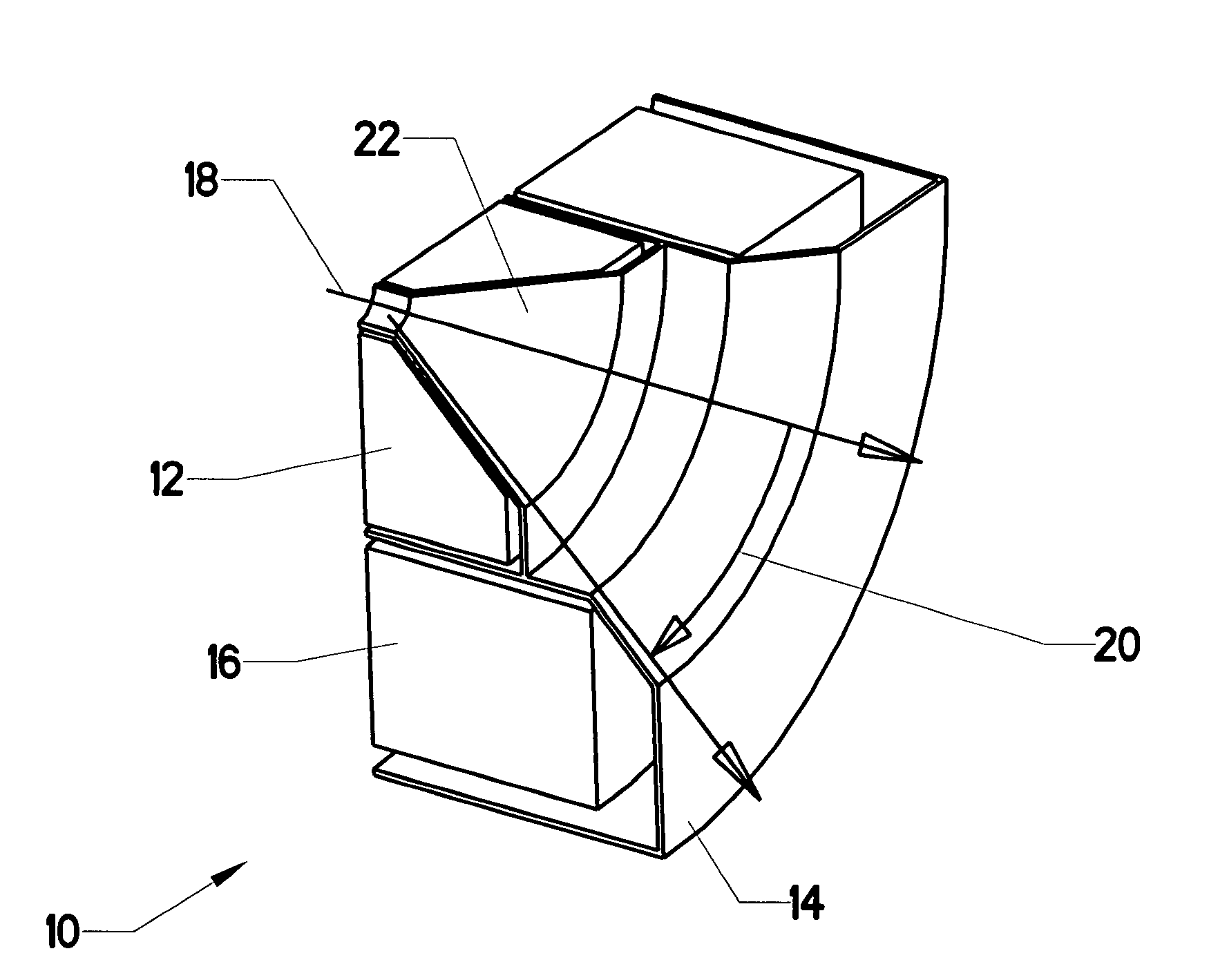
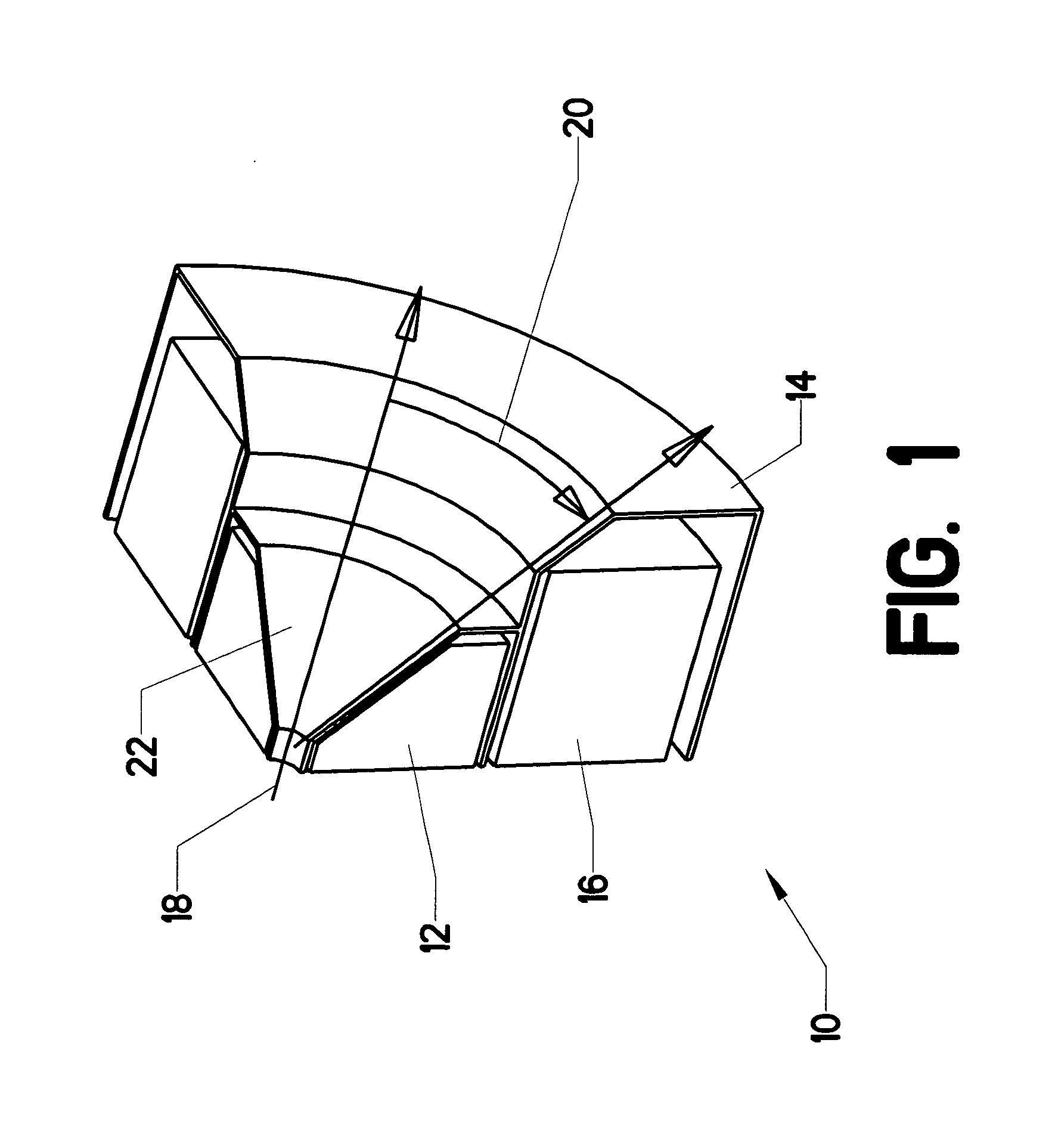
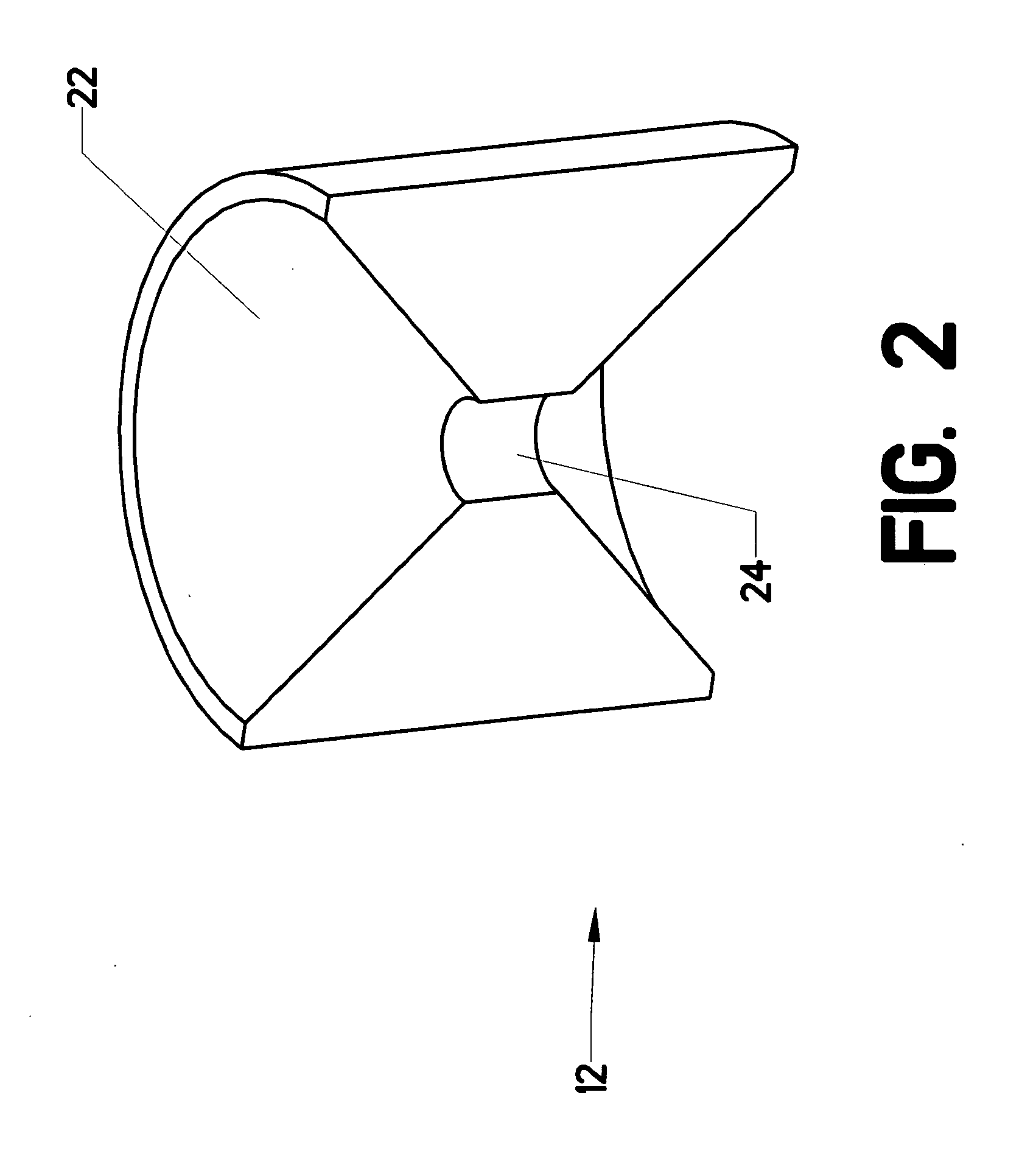
[0057]The present invention is a magnet having a conical bore. FIG. 1 is a simplified representation of ¼ of such a magnet. Conical resistive magnet 12 is created around a central axis (only 90 degrees of the 360 degree structure is shown). The resistive magnet includes a central cavity with a conical portion.

[0058]Superconducting magnet 16 surrounds conical resistive magnet 12. The result is a hybrid magnet. Both the resistive and superconducting portions are surrounded by a jacket 14. The jacket contains circulating cooling fluid and other associated hardware. Those skilled in the art will know that the actual structure of such a magnet is much more complex (including multiple jackets, insulation, cooling hardware, etc.). FIG. 1 only depicts the basic concepts.

[0059]Conical bore 22 is formed in conical resistive magnet 12. This conical bore will generate an unusual magnetic field. A beam 18 (typically comprised of photons or neutrons) entering the bore will be deflected through sc...


PUM


Abstract

An electromagnet having a conical bore. The conical bore is created by wrapping a conductor around a conically-offset helix. The cross sectional area of the conductor can be varied in order to maintain a desired current carrying capacity along the helix. A single element can be used as the conductor. The conductor can also be created by stacking a series of specially-shaped plates analogous to prior art Bitter-disks.

Description

CROSS-REFERENCES TO RELATED APPLICATIONS[0001]This is a continuation-in-part of U.S. application Ser. No. 11 / 517,229, which was filed on Sep. 7, 2006. The parent application listed the same inventors.STATEMENT REGARDING FEDERALLY SPONSORED RESEARCH OR DEVELOPMENT[0002]This invention was developed at the National High Magnetic Field Laboratory in Tallahassee, Fla. The research and development has been federally sponsored.MICROFICHE APPENDIX[0003]Not ApplicableBACKGROUND OF THE INVENTION[0004]1. Field of the Invention[0005]This invention relates to the field of electromagnets. More specifically, the invention comprises a magnet capable of producing an approximately conical field.[0006]2. Description of the Related Art[0007]The present invention proposes to create an electromagnet having a conical bore and, consequently, an approximately conical field. Several approaches may be useful for constructing such a magnet. It is therefore important for the reader to understand some known tech...

Claims


Application Information

Patent Timeline
IPC IPC(8): H01F5/00
CPCH01F5/00H01F2005/006H01F7/202
Inventor BIRD, MARK D.TOTH, JACK
Owner FLORIDA STATE UNIV RES FOUND INC
Why Eureka
Try Eureka