
Transponder device to mark implements, such as surgical implements, and method of manufacturing and using same

a transponder device and implement technology, applied in the field of rigid implement marking devices, can solve the problems of inefficient manual approach, serious adverse medical consequences, and additional surgery, and achieve the effect of enhancing leverag

Active Publication Date: 2010-02-11
TYCO HEALTHCARE GRP LP
View PDF52 Cites 38 Cited by
  • Summary
  • Abstract
  • Description
  • Claims
  • Application Information

AI Technical Summary

Benefits of technology

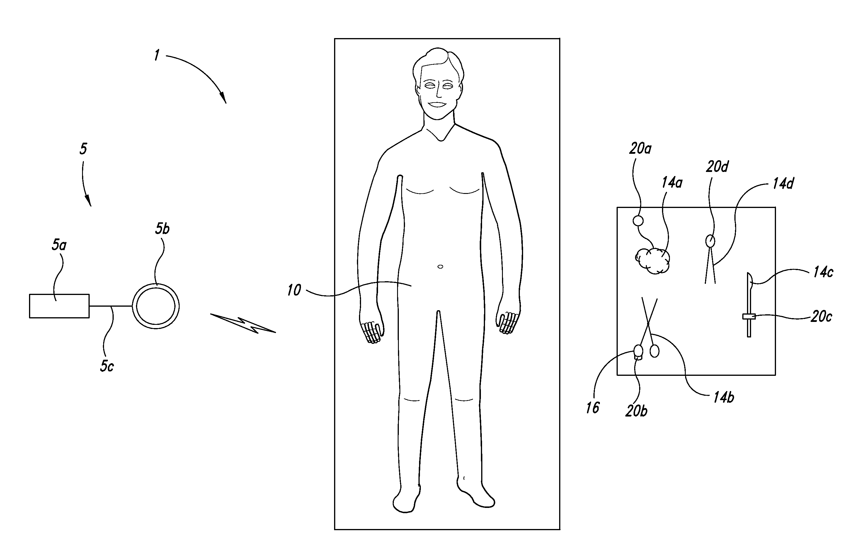
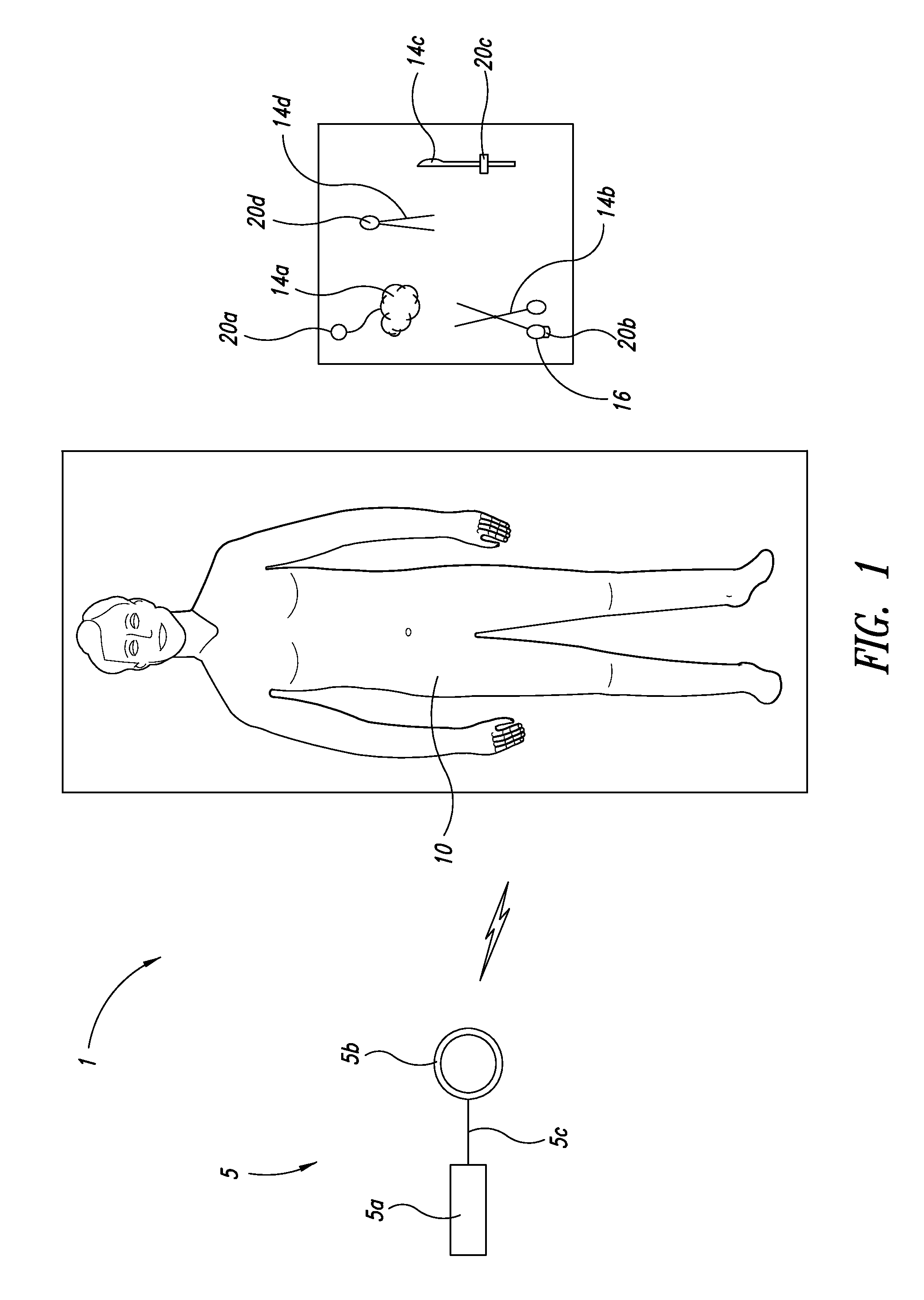
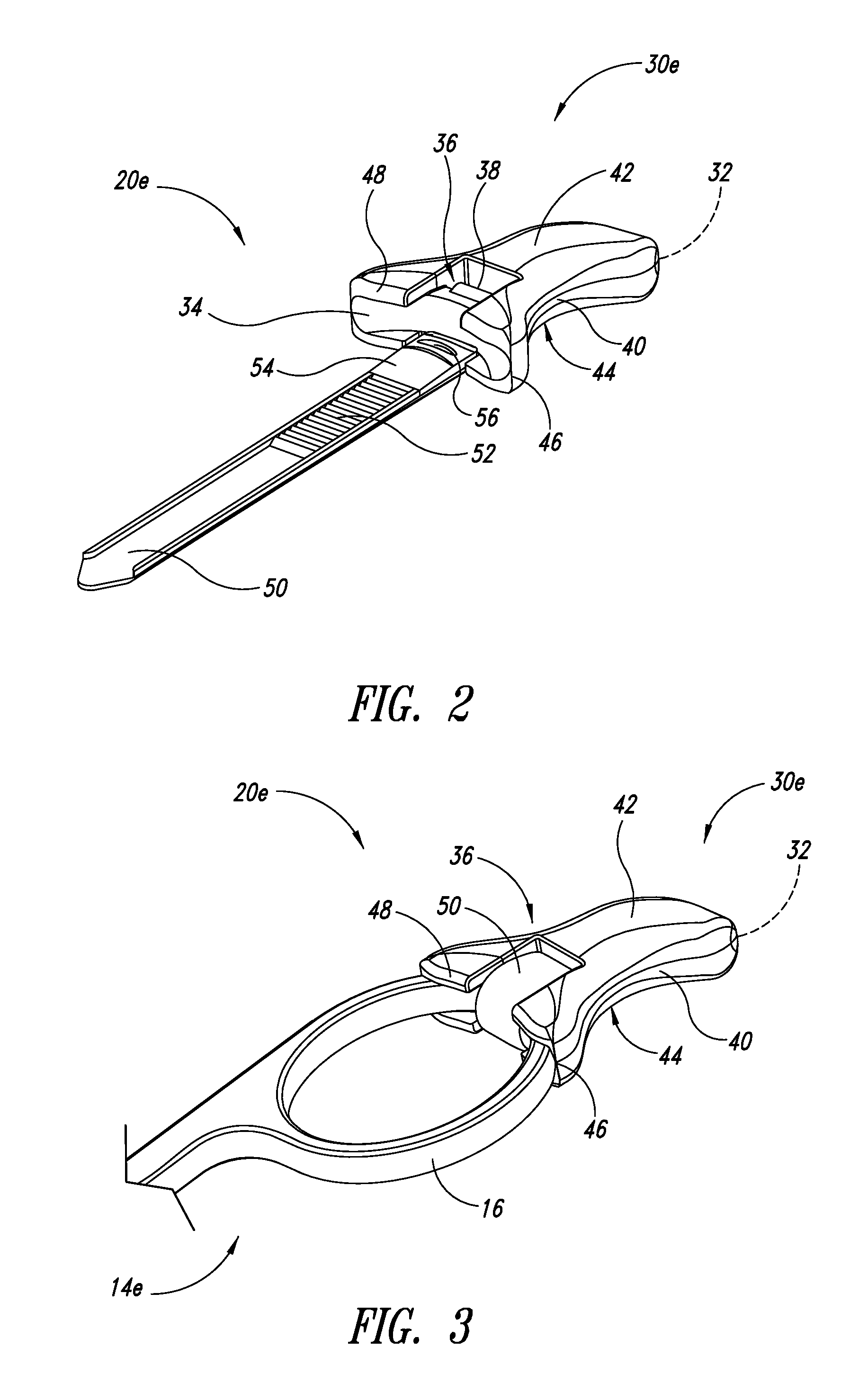
[0010]At least one embodiment may be summarized as a device to mark surgical implements including a flexible strap; and a housing attachable to a portion of a surgical implement, the housing including a transponder receiving cavity sized to receive a transponder, an implement receiving cavity sized to receive a portion of the surgical implement, a strap receiving cavity sized to receive at least a portion of the strap, and a saddle-shaped finger support surface sized and configured to receive a finger of a user and provide additional leverage for operating the surgical implement when the housing is attached to the portion of the surgical implement via the strap and the implement receiving cavity. The housing may include a base substrate and a first overmold portion that forms the implement receiving cavity. The first overmold portion may include an indentation proximate a base of the strap where the strap is fixed to the housing such that a bend radius of the strap is reduced relative to an identically sized strap without an indentation. The first overmold portion may include a raised surface proximate a base of the strap that substantially conforms with a contour of a handle of the surgical implement when the housing is attached thereto. A projection of the first overmold portion may extend beyond an interior profile of a handle of the surgical instrument to provide a gradual transition from the interior profile of the handle to a surface of the strap when the housing is attached to the handle.
[0013]The housing may further include a saddle-shaped finger support surface sized and configured to receive a finger of a user and provide additional leverage for operating the surgical implement when the housing is attached to the portion of the surgical implement via the implement receiving cavity. The overmold portion may include a first overmold location and a second overmold location, the first overmold location including an implement receiving cavity and the second overmold location retaining the transponder in the base substrate. The overmold portion may include a material different from a material of the base substrate. The overmold portion may be composed of an elastomeric material. The attachment means may include a strap and a detent mechanism that is integral to the housing. The overmold portion may include an indentation proximate a base of the strap where the strap is fixed to the housing such that a bend radius of the strap is reduced relative to an identically sized strap without an indentation. The overmold portion may include a raised surface proximate a base of the strap that substantially conforms with an interior contour of a handle of the surgical implement when the housing is attached thereto. The overmold portion may include an indentation in the raised surface such that a bend radius of the strap is reduced relative to an identically sized strap without an indentation. The overmold portion may include at least one projection extending beyond an interior profile of a handle of the surgical instrument to provide a gradual transition from the interior profile of the handle to a surface of the strap when the housing is attached to the handle.
[0018]At least one embodiment may be summarized as a transponder device selectively attachable to surgical implements, the transponder device including a transponder circuit; a framework having a number of outward extending projections that space the transponder circuit from a surface that forms a cavity of a mold in the shape of a body; the body, which body at least partially surrounds the framework and which completely surrounds the transponder circuit; and a compliant overmold interfacing with at least a first portion of the body. The framework may be a first shot of an injection molded material, the body may be a second shot of an injection molded material, and the compliant overmold may be a third shot of an injection molded material. The body of the transponder device may include a saddle-shaped finger support surface, the finger support surface sized and configured to receive a finger of a user and provide additional leverage to operate a surgical implement when the transponder device is attached to a surgical implement. The body may include an elongated strap extending therefrom and a strap receiving cavity formed therein, the strap dimensioned to encircle a portion of a surgical implement and the strap receiving cavity sized to receive at least a portion of the strap therethrough, to attach the transponder device to the surgical implement. The compliant overmold may include an implement receiving cavity formed therein, the implement receiving cavity sized to at least partially receive a portion of a surgical implement.

Problems solved by technology

Failure to locate an object before closing the patient may require additional surgery, and in some instances may have serious adverse medical consequences.
Such a manual approach is inefficient, requiring the time of highly trained personnel, and is prone to error.
However, such inexpensive devices may hinder accurate detection.
For instance, if the object and / or the device carrying the transponder is metallic or other metallic objects are present in the body, a transponder that is in fact present may not be able to be detected as a result of the metallic object acting as a Faraday shield or otherwise interfering with transponder communications.

Method used


Image

  • Transponder device to mark implements, such as surgical implements, and method of manufacturing and using same
  • Transponder device to mark implements, such as surgical implements, and method of manufacturing and using same
  • Transponder device to mark implements, such as surgical implements, and method of manufacturing and using same

Examples


Embodiment Construction

[0039]In the following description, certain specific details are set forth in order to provide a thorough understanding of various disclosed embodiments. However, one skilled in the relevant art will recognize that embodiments may be practiced without one or more of these specific details, or with other methods, components, materials, etc. In other instances, well-known structures associated with transmitters, receivers, or transceivers, and types of surgical instruments have not been shown or described in detail to avoid unnecessarily obscuring descriptions of the embodiments.

[0040]Unless the context requires otherwise, throughout the specification and claims which follow, the word “comprise” and variations thereof, such as, “comprises” and “comprising” are to be construed in an open, inclusive sense, that is as “including, but not limited to.”

[0041]Reference throughout this specification to “one embodiment” or “an embodiment” means that a particular feature, structure or character...


PUM


Abstract

A transponder device to mark a surgical implement, such as a metallic surgical instrument, is provided that comprises a transponder housing attachable to a portion of the surgical implement. The housing may include a transponder receiving cavity spaced at least 1 millimeter, and preferably at least 2 millimeters, from any portion of the surgical implement when the housing is attached to the surgical implement, and preferably includes a saddle-shaped finger support surface or a stabilizing surface sized and configured to receive a finger of a user for providing additional leverage and / or stabilizing structure when operating the implement. The housing may be removably attached to the surgical implement or permanently attached. In use, a transponder is retained in the device. Methods of manufacturing transponder devices and methods of detecting a transponder indicating the possible presence of a surgical implement are also provided.

Description

CROSS-REFERENCE TO RELATED APPLICATIONS[0001]This application claims the benefit under 35 U.S.C. §119(e) of U.S. Provisional Patent Application No. 61 / 086,727 filed Aug. 6, 2008; U.S. Provisional Patent Application No. 61 / 220,452 filed Jun. 25, 2009; and U.S. Provisional Patent Application No. 61 / 224,323 filed Jul. 9, 2009, where these (three) provisional applications are incorporated herein by reference in their entireties.BACKGROUND[0002]1. Technical Field[0003]This disclosure generally relates to a device for marking rigid implements, such as surgical instruments.[0004]2. Description of the Related Art[0005]It is often useful or important to be able to determine the presence or absence of a foreign object.[0006]For example, it is important to determine whether objects associated with surgery are present in a patient's body before completion of the surgery. Such objects may take a variety of forms. For example, the objects may take the form of instruments, for instance scalpels, s...

Claims


Application Information

Patent Timeline
Patent Type & Authority Applications(United States)
IPC IPC(8): H04Q5/22
CPCA61B19/44H04Q2213/13003A61B2019/448A61B90/90A61B90/98
Inventor BLAIR, WILLIAM A.
Owner TYCO HEALTHCARE GRP LP
Learn More