Hydraulic shovel

a shovel and hydraulic technology, applied in the field of hydraulic shovels, can solve the problems of deterioration of the front attachment weight balance, damage to control valves, pipes, etc., and achieve the effect of improving the operational stability of the front attachment and improving the weight balance of the front attachmen

Inactive Publication Date: 2010-02-11
KYB CORP
View PDF4 Cites 10 Cited by
  • Summary
  • Abstract
  • Description
  • Claims
  • Application Information

AI Technical Summary

Benefits of technology

[0009]According to this invention, the weight of the bucket control valve is not applied to the arm, and therefore the weight balance of the front attachment improves, leading to an improvemen

Problems solved by technology

However, in this type of conventional hydraulic shovel, the control valves are provided on the front attachment, and therefore the weight balance of the front attachment deteriorates due to the weight of the control val

Method used


Image

  • Hydraulic shovel
  • Hydraulic shovel
  • Hydraulic shovel

Examples


Embodiment Construction

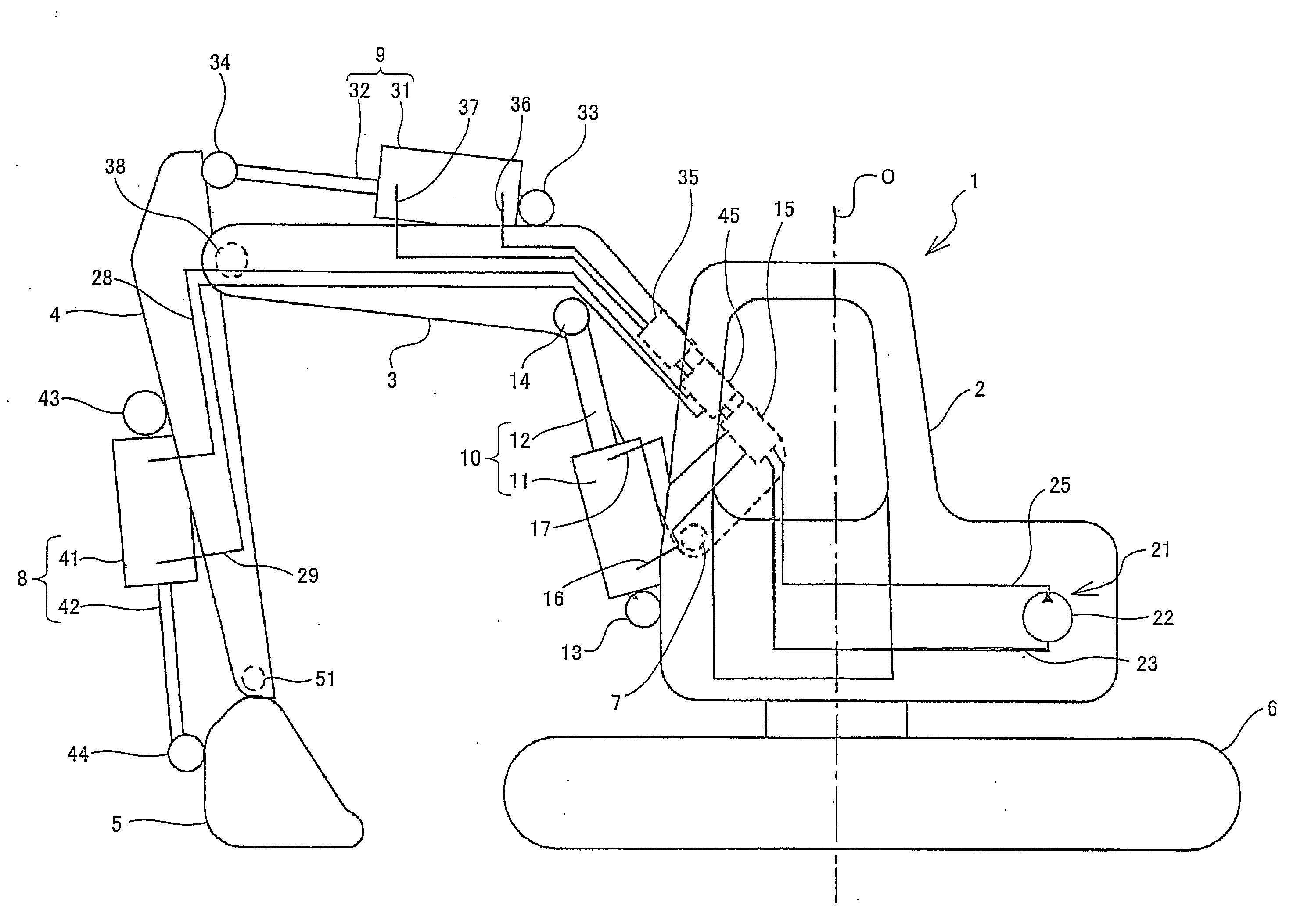
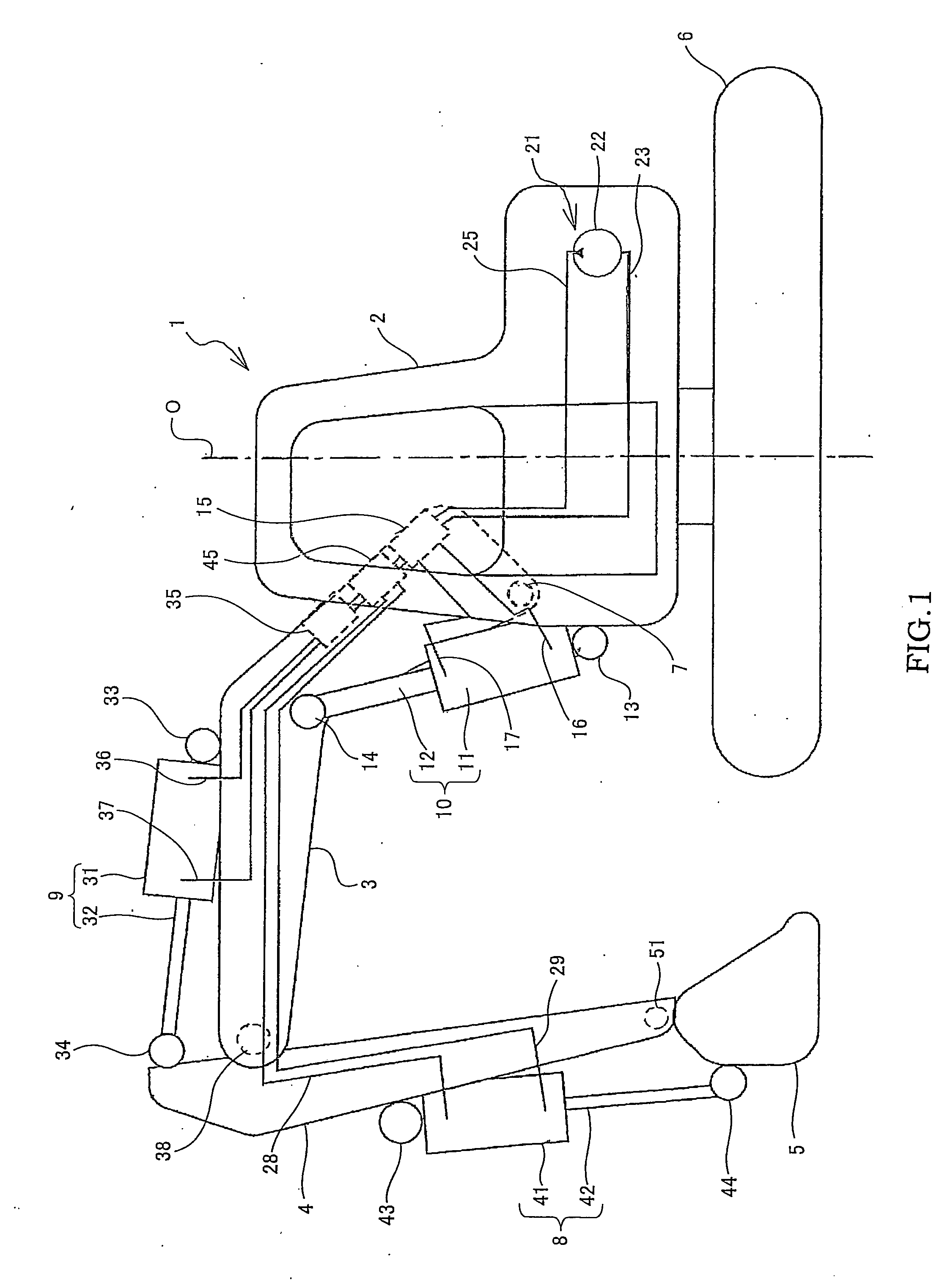
[0012]An embodiment of this invention will be described below with reference to the drawings.

[0013]As shown in FIG. 1, in a hydraulic shovel (construction machine) 1 according to an embodiment of this invention, a vehicle body (revolving body) 2 is provided revolvably on an upper portion of a traveling body 6.

[0014]The hydraulic shovel 1 includes a boom 3 connected rotatably to the vehicle body 2 via a boom support shaft 7, two boom hydraulic cylinders 10 for driving the boom 3, an arm 4 connected rotatably to a tip end of the boom 3 via an arm support shaft 38, an arm hydraulic cylinder 9 for driving the arm 4, a bucket 5 connected rotatably to a tip end of the arm 4 via a bucket support shaft 51, and a bucket hydraulic cylinder 8 for driving the bucket 5.

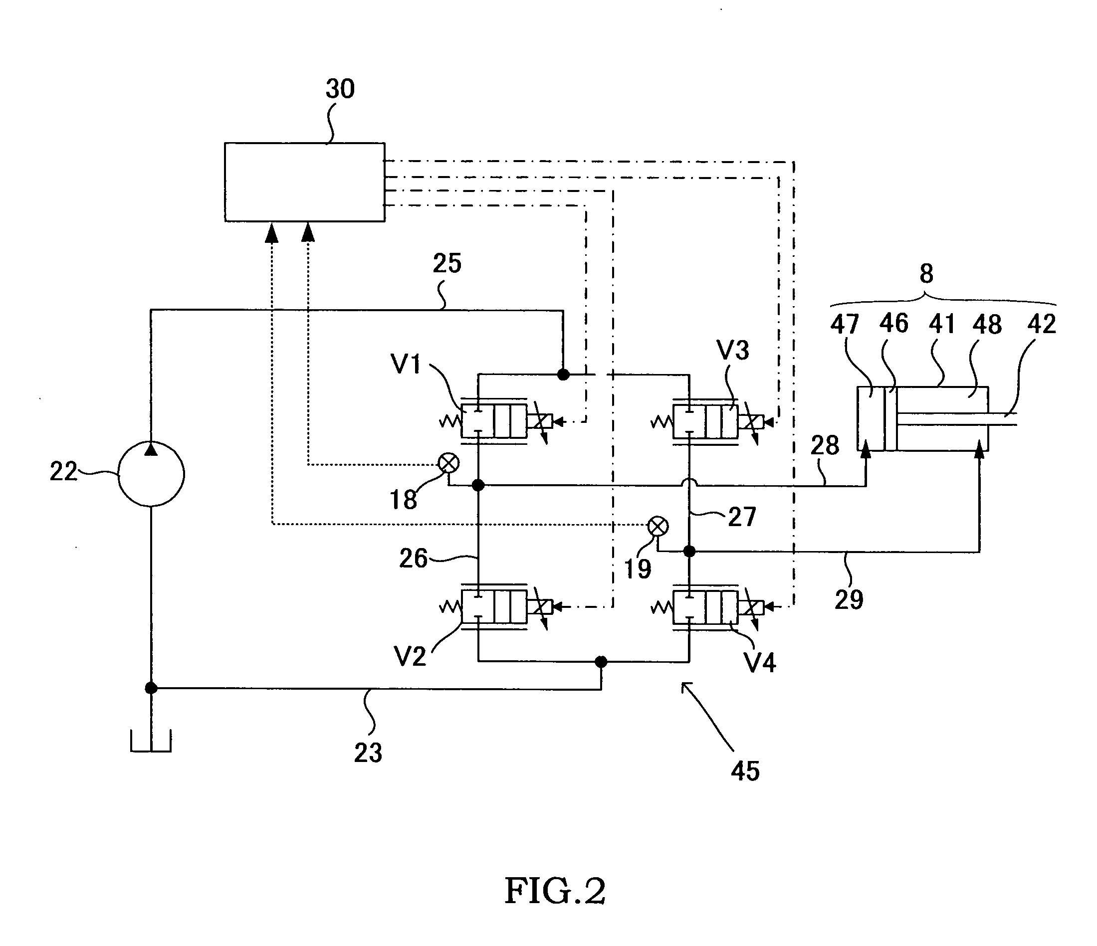
[0015]An oil pressure supply unit 21 is installed in the vehicle body 2. The hydraulic cylinders 8-10 are caused to expand and contract by working oil introduced from the oil pressure supply unit 21. By causing the hydraulic cylin...


PUM


Abstract

A hydraulic shovel (1) in which a vehicle body (2) is provided revolvably on a traveling body (6) includes a boom (3) connected rotatably to the vehicle body (2), an arm (4) connected rotatably to the boom (3), a bucket (5) connected rotatably to the arm (4), a boom hydraulic cylinder (10) that drives the boom (3), an arm hydraulic cylinder (9) that drives the arm (4), a bucket hydraulic cylinder (8) that drives the bucket (5), and a boom control valve (15), an arm control valve (35) and a bucket control valve (45) which respectively control a flow of a working oil supplied to and discharged from the respective hydraulic cylinders (8, 9, 10), wherein the boom (3) is formed to be hollow, and the bucket control valve (45) is disposed in an interior of the boom (3).

Description

TECHNICAL FIELD[0001]This invention relates to a hydraulic shovel in which a front attachment constituted by a boom, an arm, and a bucket is driven by a hydraulic cylinder.BACKGROUND ART[0002]In a conventional hydraulic shovel, discretely disposed control valves are provided in the front attachment, and a flow of working oil supplied to and discharged from respective hydraulic cylinders is controlled by the respective control valves (see JP2004-293089A and JP2005-68718A).[0003]In the hydraulic shovel disclosed in JP2004-293089A, the control valves are disposed in the vicinity of the respective hydraulic cylinders that drive the front attachment.[0004]In the hydraulic shovel disclosed in JP2005-68718A, the control valves are disposed in series on an outer side of the boom.DISCLOSURE OF THE INVENTION[0005]However, in this type of conventional hydraulic shovel, the control valves are provided on the front attachment, and therefore the weight balance of the front attachment deteriorates...

Claims


Application Information

Patent Timeline
IPC IPC(8): E02F3/85
CPCE02F9/2228E02F9/2285E02F9/2267E02F9/226E02F3/36E02F9/2264E02F3/42E02F9/14E02F9/20
Inventor KOBATA, HIROSHI
Owner KYB CORP
Why Eureka
Try Eureka