

Vacuum pumping system with a plurality of sputter ion pumps
- Summary
- Abstract
- Description
- Claims
- Application Information
AI Technical Summary
Benefits of technology
Problems solved by technology
Method used
Image

Examples
Embodiment Construction
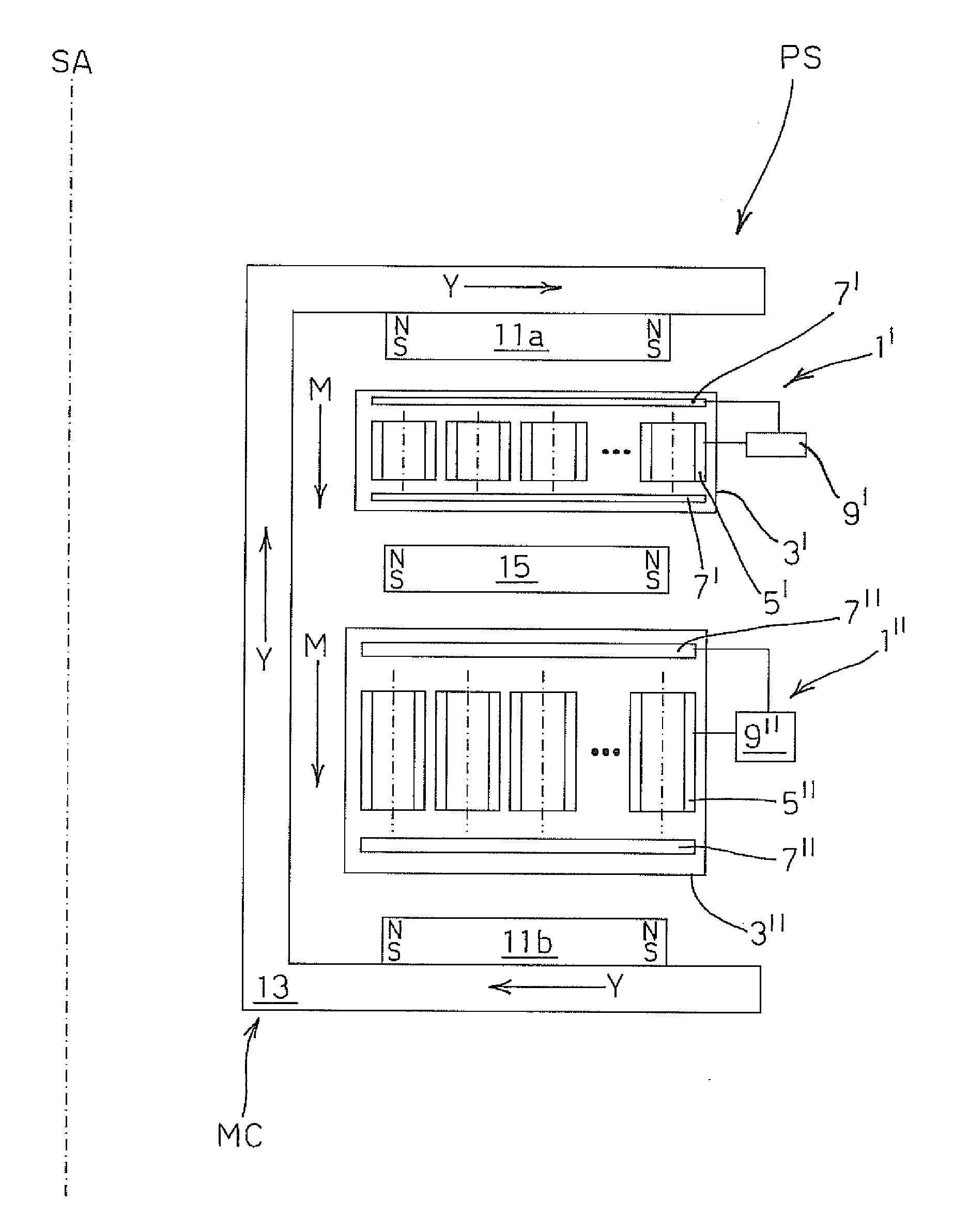
[0020]Referring to FIG. 3, there is shown a partial cross-sectional view of a pumping system PS according to the invention, comprising a pair of toroidal sputter ion pumps 1′, 1″ with symmetry axis SA.
[0021]In conventional manner, each pump 1′, 1″ comprises an anode formed by substantially cylindrical pumping cells 5′, 5″, and a cathode formed by plates 7′, 7″, e.g. of titanium, located at opposite ends of cells 5′, 5″, both the anode and the cathode being enclosed in a corresponding vacuum housing 3′, 3″. Advantageously, the pumps 1′, 1″ can be separately and independently powered by separate power supply means 9′, 9″.
[0022]According to the invention, pumping system PS further comprises a magnetic circuit MC common to both pumps 1′, 1″, the magnetic circuit MC comprising a pair of external magnets 11a, 11b, located at opposite axial ends of pumping system PS and having polarities oriented in the same direction an intermediate magnet 15 interposed between the first ion pump 1′ and t...
PUM
 Abstract
Description
Claims
Application Information