Method and apparatus for refining a molten material

a technology of molten materials and refining methods, applied in the field of refining or purifying materials, can solve the problem that the crucible can only be used on

Inactive Publication Date: 2010-02-11
ELKEM SOLAR
View PDF6 Cites 2 Cited by
  • Summary
  • Abstract
  • Description
  • Claims
  • Application Information

AI Technical Summary

Benefits of technology

[0010]Thus, the invention provides a streamlined production process in which the furnace vessel is heated and the ingot cast, but there is no ingot contact within the vessel and so the ingot can be removed and the vessel refilled. The vessel does not need to be cooled between ingot castings.
[0012]The method has the advantage that the impurity level in the ingot decreases relative to the remainder of the melt, as the ingot forms. Then the ingot is removed from the vessel or crucible and the remaining liquid with high impurity content is poured off and possibly reprocessed. The vessel does not have to be destroyed and can be re-used. The nucleation site is simplified from a crucible to a surface of a plate or several plates arranged side by side. The plate or the plates arranged side by side consist of several plates in a layered structure. The cooled surface may be formed with discontinuities to help ensure adhesion of the ingot.
[0017]The solidification process may be optimized by combining forces that move the impurities with flow patterns and settling forces. Molten silicon with a high content of impurities with high density will flow from the solidification interface towards the bottom. A similar picture will occur for the heavy particles, while particles with little or no difference in density will follow the flow in the vessel. These mechanisms can be optimized more easily if solidification takes place from the top of a bath to bottom.
[0021]Preferably, the cooling plate includes a plurality of layers including a heat conductive layer in operative contact with cooling means, and a contact layer for making contact with the molten material. Preferably, the contact layer and any intermediate layer are made from heat conductive but chemically inert and temperature resistant materials such as graphite, silicon nitride, silicon carbide, silica, silicon oxynitride, alumina or other ceramic oxides. The heat conductive layer may be of a metal, such as copper, aluminium or some suitable alloy. In addition, a heating layer such as a layer of electric resistance heating elements or an induction heated layer may be incorporated in between the other layers. This may provide better control of the cooling process.

Problems solved by technology

A disadvantage of today's approach is that the quartz crucible can be used only once, since it is destroyed due to a phase transition of the crucible material during cool down of the silicon ingot (and the crucible).

Method used


Image

  • Method and apparatus for refining a molten material
  • Method and apparatus for refining a molten material
  • Method and apparatus for refining a molten material

Examples


Embodiment Construction

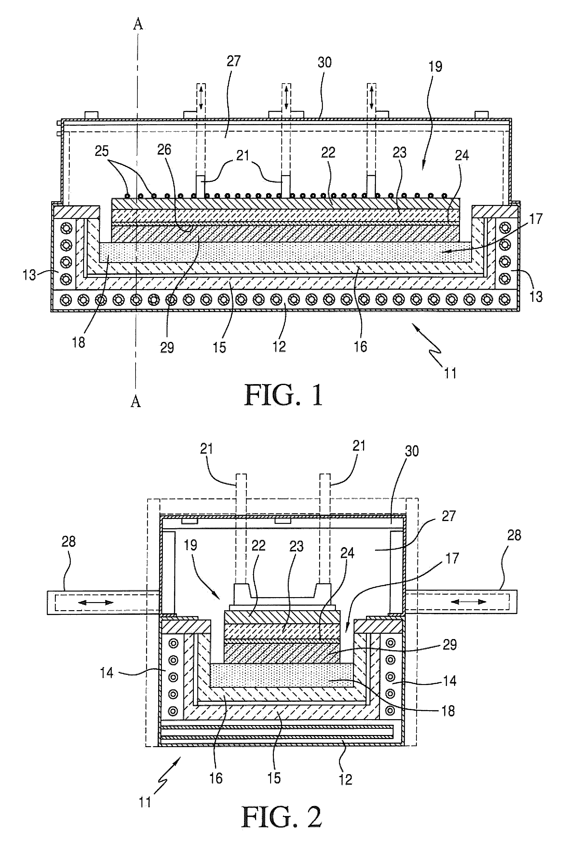
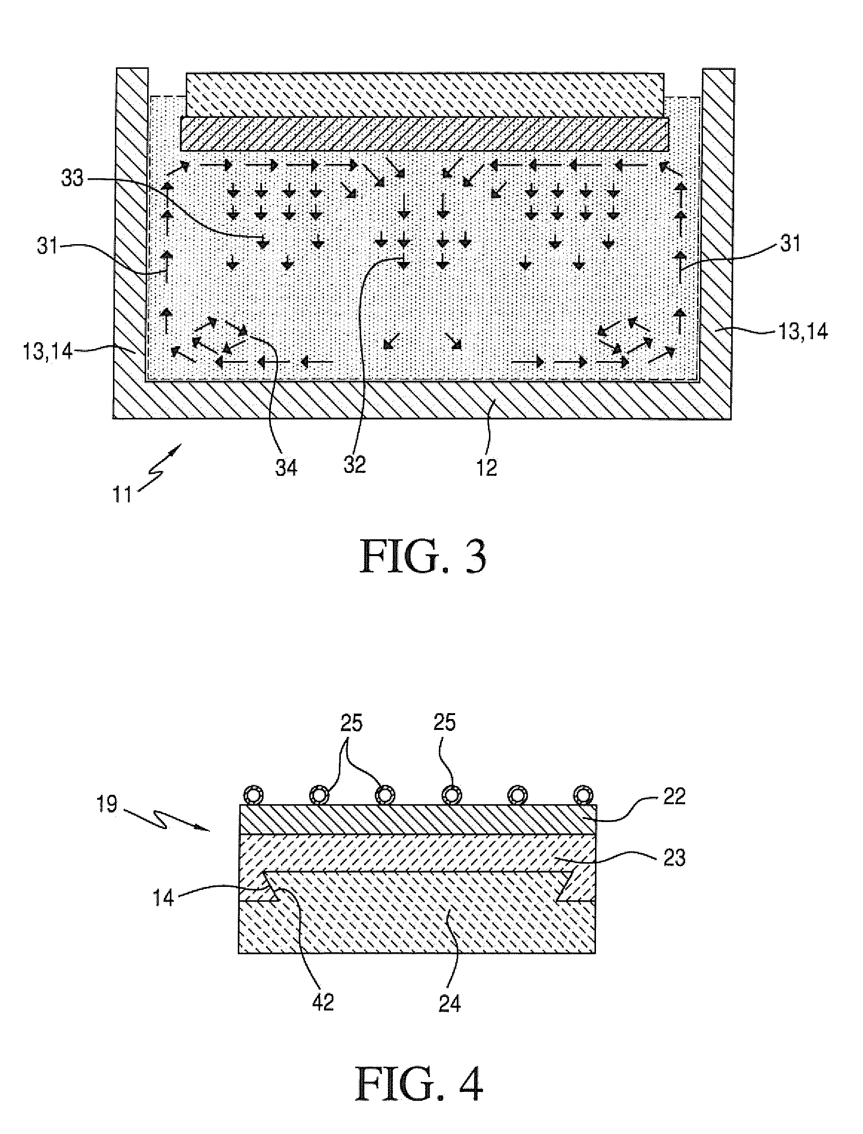
[0008]According to one aspect of the invention, there is provided a method of refining a material which comprises the steps of: forming a melt of the material in a vessel; bringing a cooled surface into contact with the surface of the melt, allowing the molten material to solidify and adhere to the cooled surface; and progressively solidifying the molten material downwards to form a solid ingot of the material adhering to the cooled surface.

[0009]Although defined as a method of refining, the invention could also be considered to be a method of directional solidification.

[0010]Thus, the invention provides a streamlined production process in which the furnace vessel is heated and the ingot cast, but there is no ingot contact within the vessel and so the ingot can be removed and the vessel refilled. The vessel does not need to be cooled between ingot castings.

[0011]Preferably, the walls and bottom of the vessel are heated. Preferably, the melt is maintained in an inert or controlled at...


PUM

PropertyMeasurementUnit
meltaaaaaaaaaa
temperatureaaaaaaaaaa
resistivityaaaaaaaaaa

Abstract

A method for the directional solidification of silicon or other materials. A cooled plate is lowered into a silicon melt and an ingot of solid silicon is solidified downwards.

Description

CROSS-REFERENCE TO RELATED APPLICATIONS[0001]This is a Divisional of U.S. patent application Ser. No. 11 / 916,898, filed Dec. 7, 2007, which was a 371 of PCT / NO2006 / 000174 filed May 10, 2006, which claimed the priority of NO 2005 / 2832 filed Jun. 10, 2005, all three Applications are incorporated herein by reference.FIELD OF INVENTION[0002]The present invention is concerned with refining or purifying a material which can be melted and solidified. It is particularly, but not exclusively, applicable to the purification of metals, especially silicon, for example refining of silicon feedstock for the manufacture of solar cells.BACKGROUND ART[0003]Directional solidification is widely used in the Photo Voltaic [PV] industry to produce ingots, which are sliced into wafers and later processed to become solar cells. The current state of the art is dominated by a system where silicon is solidified directionally from the bottom to the top in a crucible of quartz.[0004]The same principle can be us...

Claims


Application Information

Patent Timeline
Patent Type & Authority Applications(United States)
IPC IPC(8): C01B33/021C01B33/02C01B
CPCC30B11/003C30B29/06Y10T117/1032Y10T117/1036Y10T117/1044Y10T117/1088Y10T117/108Y10T117/10Y10T117/1024Y10T117/1068Y10T117/1072C30B15/10C30B35/00
Inventor FRIESTAD, KENNETH
Owner ELKEM SOLAR
Why Eureka
Try Eureka