
Safety Scalpel With Replaceable Blade Cartridge And Safety Brake

a safety brake and scalpel technology, applied in the field of scalpels, can solve the problems of potentially life-threatening infections the health care workers are actually experiencing an increase in occupational injuries and illnesses, and the infection of each of these pathogens, and achieve the effect of convenient mounting

Active Publication Date: 2010-02-11
MEDIPURPOSE PTE
View PDF27 Cites 140 Cited by
  • Summary
  • Abstract
  • Description
  • Claims
  • Application Information

AI Technical Summary

Benefits of technology

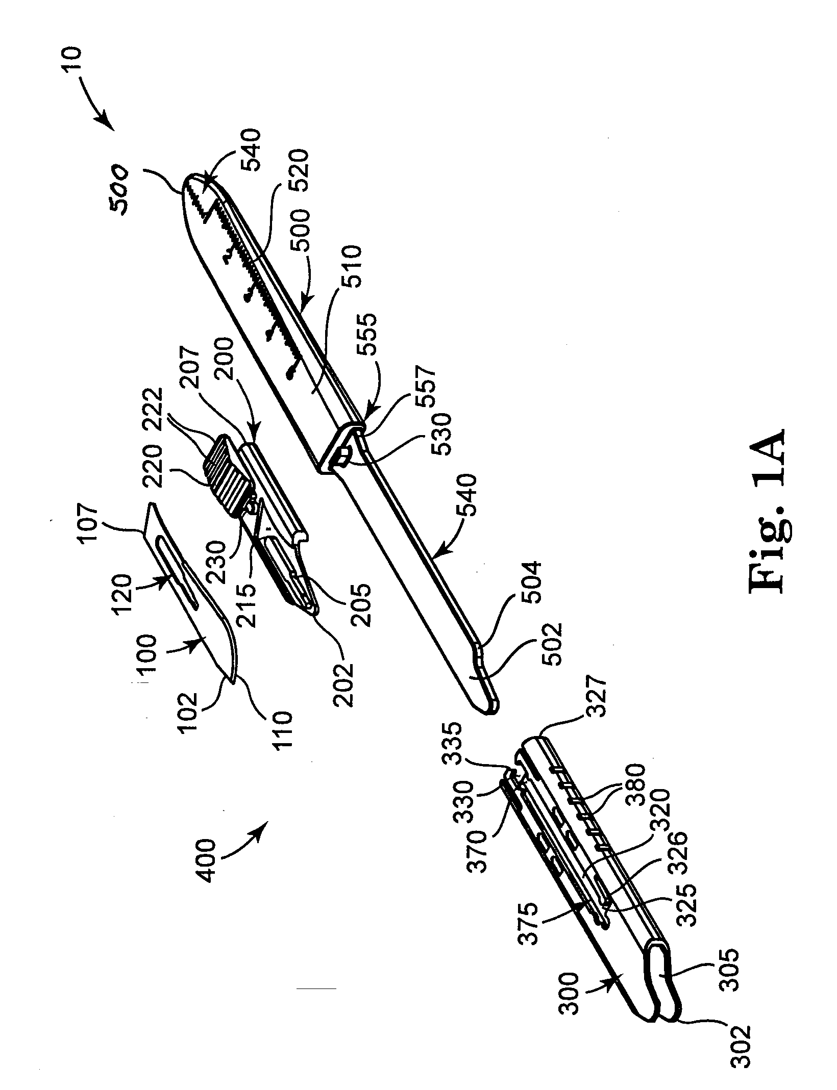
The present invention is an improvement over conventional scalpels by providing a safety scalpel that incorporates a reusable metal scalpel handle and a disposable blade cartridge. The blade cartridge can be easily mounted and released from the scalpel handle, and is securely locked in place. The blade cartridge can be a standalone mini-scalpel or a part of a larger scalpel. The safety scalpel includes a blade holder, blade guard, and a locking mechanism for securely locking the blade cartridge to the scalpel handle. The blade cartridge can be easily detached and replaced. The safety scalpel provides a safer alternative to conventional scalpels and is easy to use and detach.

Problems solved by technology

Although it is possible to prevent or reduce health care worker exposure to these hazards, health care workers are actually experiencing increasing numbers of occupational injuries and illnesses.
Most reported needlestick and sharps injuries involve nursing staff; but laboratory staff, physicians, housekeepers, and other health care workers are also injured.
Some of these injuries expose workers to bloodborne pathogens that can cause infection.
Infections by each of these pathogens are potentially life threatening, yet preventable.
The emotional impact of needlestick and sharps injuries can be severe and long lasting, even when a serious infection is not transmitted.
This impact is particularly severe when the injury involves exposure to HIV.
In addition to the exposed health care worker, colleagues and family members may suffer emotionally.
Although each of these characteristics is desirable, some are not feasible, applicable, or available for certain health care situations.
The process of mounting and dismounting of the blade is a difficult and dangerous procedure, which exposes the medical practitioner to potential injury from the exposed blade and contamination due to blood that may be present on the blade.
Further, sharps injuries may also occur during an operation as the surgeon passes the exposed scalpel to a colleague.
Surgeons who have developed a feel for the shape and weight of the metal handle dislike the current disposable safety scalpels as, among other things, the plastic handle is too light and feels “different.” During use, the plastic handle of the scalpel incurs undesirable flexibility than that of a metal handle scalpel.
In addition, the disposable safety scalpel is significantly more expensive than the regular disposable blade.
These two factors currently limit the adoption of safety scalpels in the healthcare industry.

Method used


Image

  • Safety Scalpel With Replaceable Blade Cartridge And Safety Brake
  • Safety Scalpel With Replaceable Blade Cartridge And Safety Brake
  • Safety Scalpel With Replaceable Blade Cartridge And Safety Brake

Examples


first embodiment

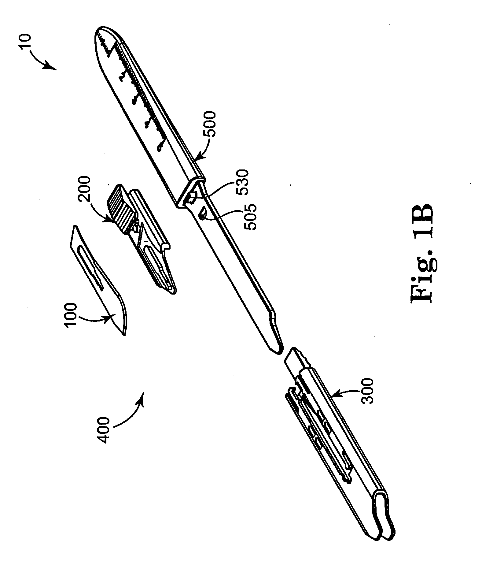
[0100]In a first embodiment, the blade guard 300 of FIGS. 3A and 3B is secured to the scalpel handle 500 of FIG. 1A. That is, there is no aperture 505 (see FIG. 1B).

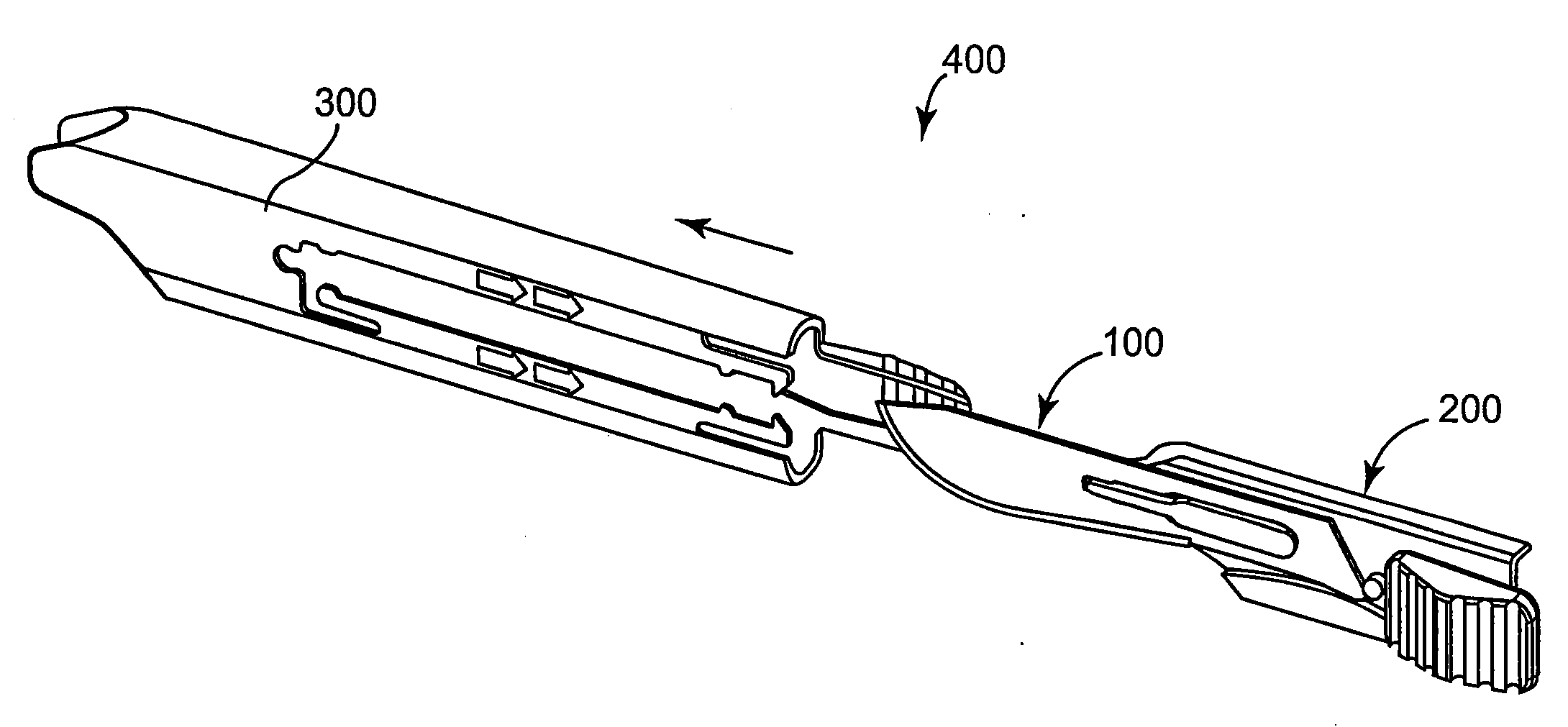
[0101]The blade guard 300 in this first embodiment is removed by having the holder knob 220 placed in the rear retaining slot 370, such that the blade 100 is in the closed position and does not extend from the blade guard 300. The holder knob 220 can be slid slightly further towards the proximal end 307 of the blade cartridge 400 (e.g., proximal end 307 of the blade guard 300), or towards the approximate midpoint 555. When the holder knob 220 slides in this direction, the catch 335 moves away from the extending member 530 of the scalpel handle 500. This can release the blade cartridge 400 from the scalpel handle 500. Then, the user need only slide the entire blade cartridge 400 towards the distal end 502 of the scalpel handle 500, or off the scalpel handle 500.

second embodiment

[0102]In a second embodiment, the scalpel handle 500 includes an aperture 505 in proximity to the extending member 530, preferably slightly offset towards the distal end 502. In this embodiment, the blade cartridge 400 (e.g., the blade guard 300) further includes the locking mechanism 355 about its rear face 315.

[0103]Once the locking mechanism 355 is removed from the aperture 505, the catch 335 can be released from the extending member 530, as described above. Then, the blade cartridge 400 is loose enough to be released from the scalpel handle 500. In essence, the latching assembly 345 is an additional safety feature to help ensure the blade cartridge 400 does not mistakenly release from the scalpel handle.

[0104]The rear face 315 of the blade cartridge 400 (e.g., the rear face 315 of the blade guard 300) matches up with the rear face 515 of the scalpel handle 500. When the blade cartridge 400 is secured to the scalpel handle 500, the latching assembly 345 is adapted to engage the a...


PUM

PropertyMeasurementUnit
frictional forceaaaaaaaaaa
movementaaaaaaaaaa
resilientaaaaaaaaaa

Abstract

A safety scalpel that incorporates a reusable metal scalpel handle (500) similar in shape and feel to the conventional metal handle preferred by most surgeons, and a disposable blade cartridge (300) that covers the blade (100) before, during and after use, and is easily mounted and released from the scalpel handle. The blade cartridge includes a blade (100) with similar cutting profiles as standard surgical blades, a blade holder that is permanently fixed to the blade, and a blade guard (300) that covers the blade and within which the blade holder (200) is able to slide. The scalpel handle is reusable, while the blade cartridge is disposable. The blade cartridge is attachable and detachable from the scalpel handle and may include means (1301) to prevent movement of the blade except when the reusable handle is in place. A safety latch feature (2230) is provided.

Description

CROSS REFERENCE TO RELATED APPLICATION AND CLAIM OF BENEFIT[0001]This application is a continuation-in-part application of U.S. patent application Ser. No. 11 / 259,939, filed on 26 Oct. 2005, which claims priority to U.S. Provisional Patent Application No. 60 / 623,741, filed on 29 Oct. 2004.FIELD OF THE INVENTION[0002]The present invention relates generally to scalpel devices and, in particular, to safety scalpels for medical use.BACKGROUND OF THE INVENTION[0003]Health care is the second fastest growing sector of the U.S. economy, employing over 12 million workers. Health care workers face a wide range of hazards on the job, including needlestick and sharps injuries, back injuries, latex allergies, violence, and stress. Although it is possible to prevent or reduce health care worker exposure to these hazards, health care workers are actually experiencing increasing numbers of occupational injuries and illnesses. Rates of occupational injury to health care workers have risen over the p...

Claims


Application Information

Patent Timeline
Patent Type & Authority Applications(United States)
IPC IPC(8): A61B17/3213B23P11/00
CPCA61B17/3213Y10T29/49826A61B2019/4805A61B2017/32113A61B17/3215A61B2090/0801
Inventor YI, PATRICKLE, HONG-MINH
Owner MEDIPURPOSE PTE
Learn More