
Virtual computer system, error recovery method in virtual computer system, and virtual computer control program

Inactive Publication Date: 2010-02-11
HITACHI LTD
View PDF8 Cites 24 Cited by
  • Summary
  • Abstract
  • Description
  • Claims
  • Application Information

AI Technical Summary

Benefits of technology

[0016]Therefore, an object of the present invention is to provide a virtual computer system and an error recovery method which make it possible to recover from a cache memory error without needing to add hardware and mounting an error recovery unit on a guest program, and a virtual computer control program which implements this method. The object and other objects and novel features of the present invention will be elucidated from the following description and accompanying drawings.
[0020]According to representative embodiments of the present invention, a high reliability system which makes long time continuous operation possible even if a cache memory error occurs can be provided in a virtual computer system. Furthermore, it is possible to provide a low-cost secure cache memory error recovery function without needing to add hardware and mount an error recovery unit on a guest program, by providing an error recovery function for the cache memory in the virtual computer control program.

Problems solved by technology

Therefore, it can be said that it is not easy to apply the technique to the cache memory for recovery from a cache memory error.
However, it is not desirable in the cost aspect to add hardware for implementing recovery from a cache memory error in, for example, a virtual computer system which can be applied to low-end PC servers as well.
As for recovery from a cache memory error conducted by software as well, therefore, it is not real and desirable to request all of these guest programs to mount a cache memory error recovery function enough to achieve the long time continuous drive.

Method used


Image

  • Virtual computer system, error recovery method in virtual computer system, and virtual computer control program
  • Virtual computer system, error recovery method in virtual computer system, and virtual computer control program
  • Virtual computer system, error recovery method in virtual computer system, and virtual computer control program

Examples


embodiment

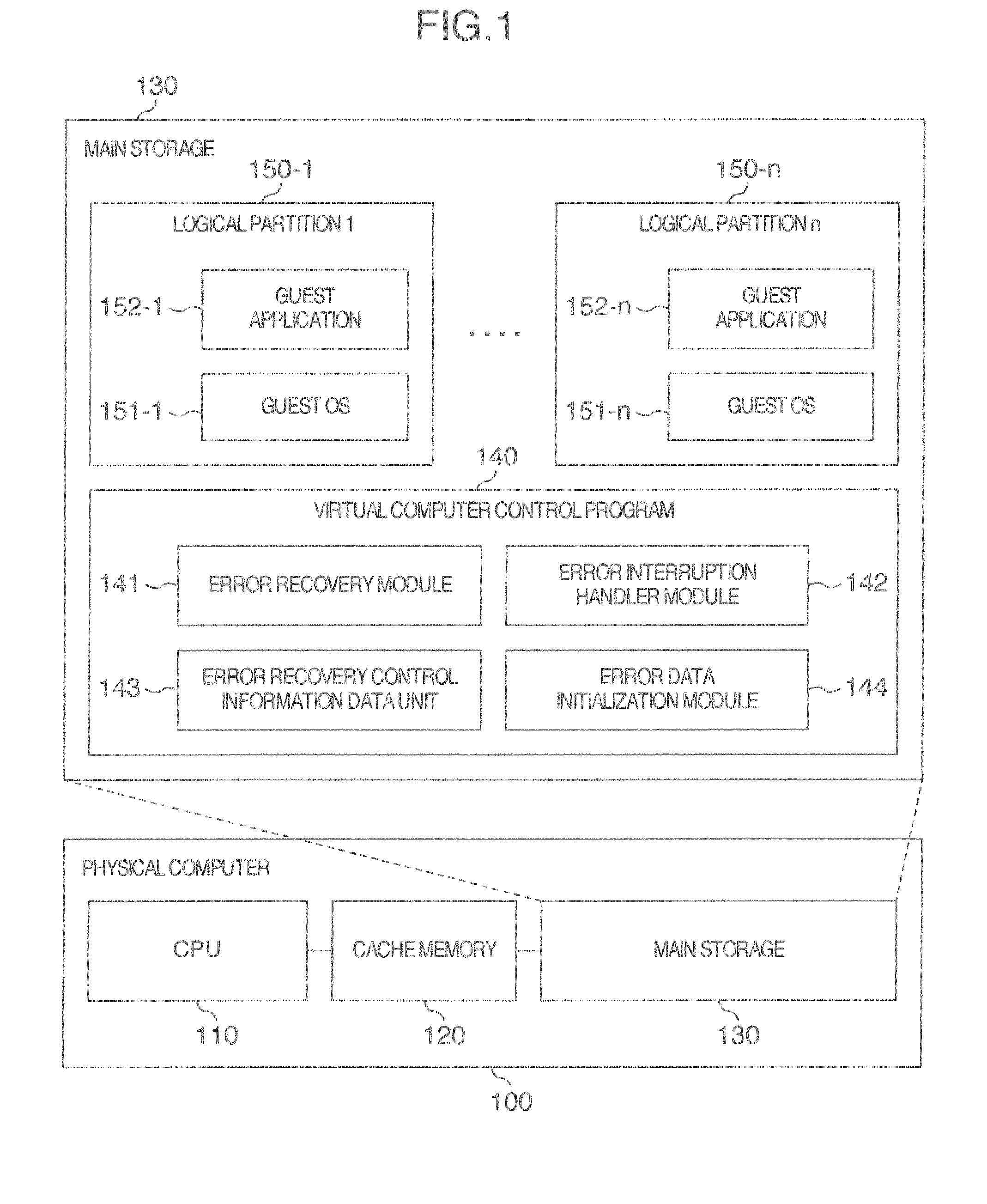
[0043]Hereafter, a virtual computer system which is an embodiment of the present invention will be described. FIG. 1 is a block diagram showing an example of a virtual computer system which is an embodiment of the present invention.

[0044]In one physical computer 100 in the virtual computer system according to the present embodiment, a virtual computer control program 140 constitutes a plurality of logical partitions 150 (150-1 to 150-n). In each of the logical partitions 150, a guest OS 151 (151-1 to 151-n) and a guest application 152 (152-1 to 152-n) can operate (hereafter, the guest OS 151 and the guest application 152 are referred to collectively as guest program in some cases). In other words, a virtual computer system in which guest programs can operate in the logical partitions 150 under the control of the virtual computer control program 140 is constituted in the physical computer 100.

[0045]The physical computer 100 includes a CPU 110, a main storage 130, and a cache memory 1...


PUM


Abstract

A virtual computer system executes a virtual computer control program on a physical computer and thereby causes guest programs on the logical partitions, respectively. The virtual computer control program includes an error recovery module to periodically recover from an error in a cache memory, an error interruption handler module responsive to an interruption notice caused by an error which has occurred in the cache memory, to recover from an error in the cache memory, and an error data initialization module to recover from an error in the cache memory with shutdown or restart of one of the logical partitions as a momentum. And the virtual computer control program conducts recovery processing from an error in the cache memory.

Description

INCORPORATION BY REFERENCE[0001]The present application claims priority from Japanese application JP2008-203968 filed on Aug. 7, 2008, the content of which is hereby incorporated by reference into this application.BACKGROUND OF THE INVENTION[0002]The present invention relates to an error recovery technique in a virtual computer system, and in particular to a technique which is effective to application to an error recovery technique in a cache memory.[0003]As a conventional technique making it possible to operate OSs (operating systems) which have operated separately in a plurality of physical computers and software programs which operate on the OSs, by using one physical computer, there is the virtual computer technique.[0004]In the virtual computer technique, for example, a virtual computer control program called hypervisor logically divides one physical computer into a plurality of logical partitions. The virtual computer control program assigns computer resources (a CPU (central ...

Claims


Application Information

Patent Timeline
IPC IPC(8): G06F11/14
CPCG06F11/0712G06F11/073G06F11/1484G06F11/106G06F12/0802G06F11/0793
Inventor KOBAYASHI, TAKASHITAKESHITA, AKIRAYAMAMOTO, MITSUONAGASHIMA, HIROMI
Owner HITACHI LTD
Learn More