Fluid power distribution and control system

a technology of power distribution and control system, applied in the direction of fluid clutch, fluid-pressure actuator, fluid coupling, etc., can solve the problems of energy loss, unsatisfactory compromise, and the overall efficiency of such a system to reduce to 30%

Active Publication Date: 2010-02-18
DANFOSS PAUER SOLYUSHENS APS
View PDF11 Cites 40 Cited by
  • Summary
  • Abstract
  • Description
  • Claims
  • Application Information

AI Technical Summary

Benefits of technology

[0014]Individual fluid supplies from a Digital Displacement pump can be switched quickly from being controlled by a flow demand t

Problems solved by technology

In systems with a single pump and multiple actuators there is always undesirable compromise given the practical impossibility of matching the instantaneous pressure requirements of all of the active actuators to the single pressure supply.
The difference between this pressure and the actual pressure required o

Method used


Image

  • Fluid power distribution and control system
  • Fluid power distribution and control system

Examples


Embodiment Construction

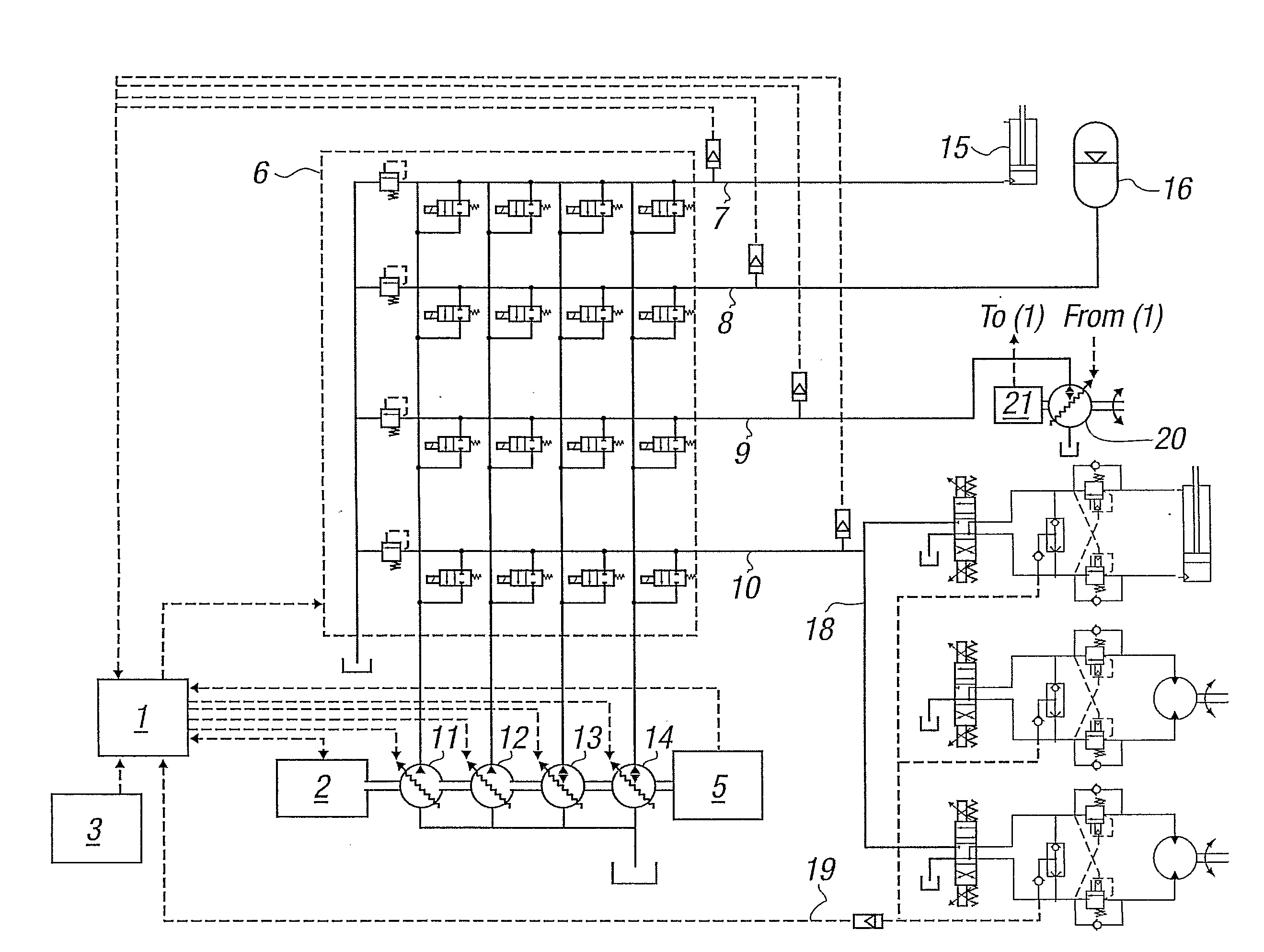
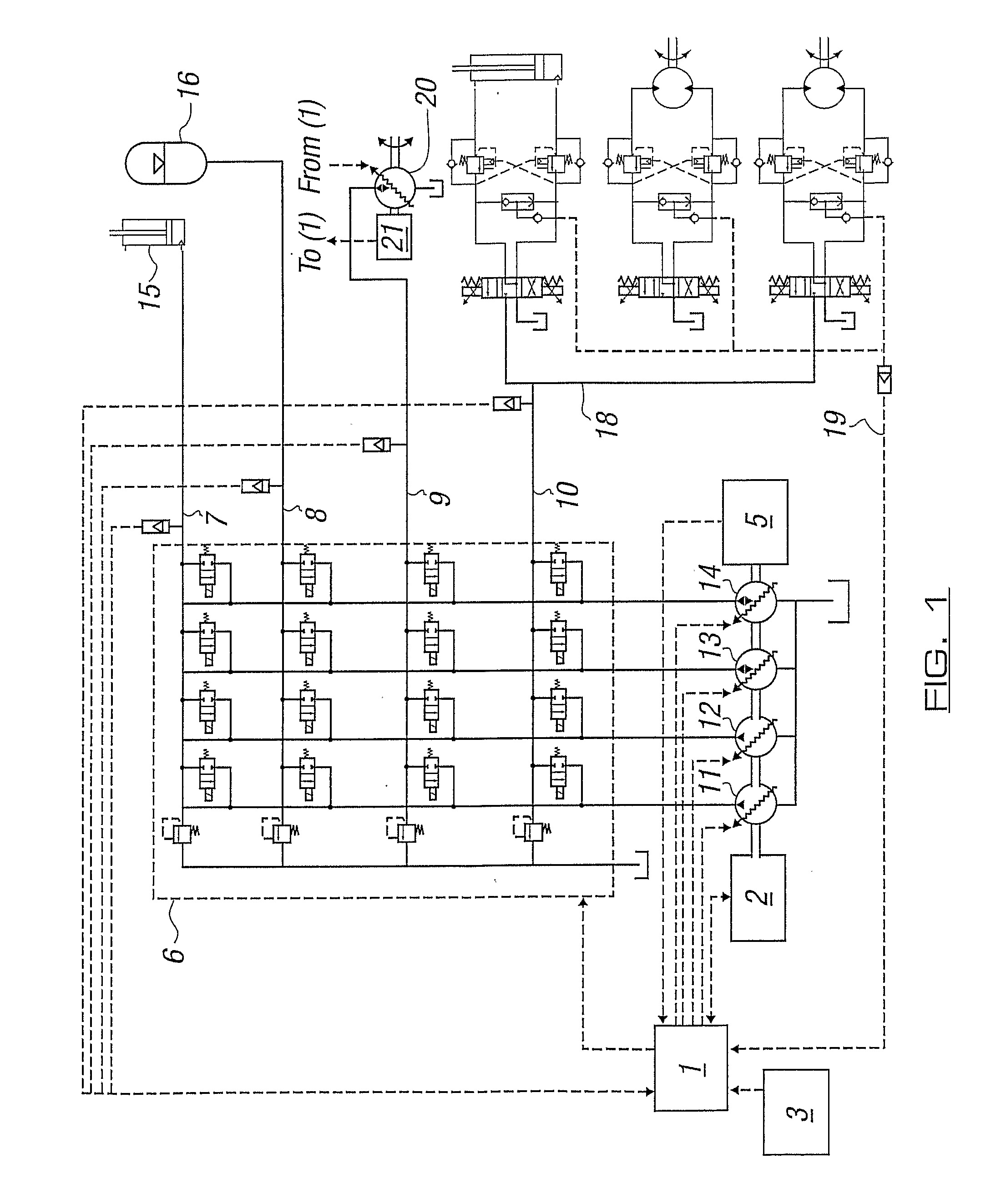
[0021]The drawing shows a pump / motor with four independent fluid supplies, two of which 11, 12 are pump outlets, two of which 13, 14 are pump / motor outlets, and each of which is controlled by a controller 1. Mechanical power comes into the pump / motor unit via its shaft from a prime mover 2, which may take a speed demand signal from the controller 1.

[0022]The switching circuit 6 in this embodiment consists of digital solenoid valves in a matrix arrangement such that any of the fluid outlets of the pump / motor 11, 12, 13, 14 may be coupled to any of the load ports 7, 8, 9, 10. These valves are controlled by the controller 1. Each of the load ports 7, 8, 9, 10 is protected from overpressure by a safety relief valve.

[0023]The first load port 7 is connected to a single acting ram 15. The pressure supply has a pressure sensor feeding a signal to the controller. The operator demands a certain pressure be maintained on the ram, however the system is also capable of controlling the flow to th...


PUM


Abstract

A fluid power system comprises a pump with multiple independently variable outlets (11, 12, 13, 14), each of which is capable of delivering fluid in individually controllable volume units and a plurality of hydraulic loads (15, 16, 18, 20). A system of switching valves is configured to create fluid connections between the pump outlets and the loads. A control system commands both the pump and the switching valves, so as to create valve state combinations to satisfy load conditions as demanded by an operator The number of pump outlets (11, 12, 13, 14) connected to one or more of the loads (15, 16, 18, 20) is changeable to satisfy the flow required of the load due to the operator demand, each pump outlet being commanded to produce a flow depending on the status of other outlets connected a load to which the outlet is connected and the operator demand for that load.

Description

BACKGROUND TO THE INVENTION[0001]This invention relates to a fluid power system.[0002]In their most basic form, fluid power systems generally consist of a pressurised fluid source, a motion control valve and an actuator such as a ram or a motor. Systems are typically generalised by attaching further motion control valves in parallel to the first so that additional actuators can be moved with the power supplied by the fluid source. Because most actuators have a fixed linear or rotary movement per unit of fluid displacement, the force they exert is directly proportional to the pressure supplied. In systems with a single pump and multiple actuators there is always undesirable compromise given the practical impossibility of matching the instantaneous pressure requirements of all of the active actuators to the single pressure supply.[0003]In the case of the state-of-the-art “load sensing” system, the displacement of a variable displacement pump is controlled such as to maintain its outpu...

Claims


Application Information

Patent Timeline
IPC IPC(8): F16D31/02
CPCF15B11/0445F15B2211/7058F15B11/17F15B2211/20546F15B2211/20569F15B2211/20576F15B2211/265F15B2211/3127F15B2211/327F15B2211/5059F15B2211/6052F15B2211/6054F15B2211/6313F15B2211/6346F15B2211/7052F15B2211/7053F15B11/162
Inventor RAMPEN, WILLIAM HUGH SALVINCALDWELL, NIALL JAMESSTEIN, UWE BERNHARD PASCALLJOLY, PIERREFIELDING, MICHAEL RICHARD
Owner DANFOSS PAUER SOLYUSHENS APS
Why Eureka
Try Eureka