Feeding device for liquid materials

a technology of liquid materials and feeding devices, which is applied in the direction of positive displacement liquid engines, piston pumps, separation processes, etc., can solve the problems of high manufacturing cost, unfavorable field workers, and complicated structure of conventional mechanical or pneumatic pumps, and achieves cheap manufacturing cost and simplified structure.

Inactive Publication Date: 2010-02-18
LU SHUN TSUNG
View PDF3 Cites 11 Cited by
  • Summary
  • Abstract
  • Description
  • Claims
  • Application Information

AI Technical Summary

Benefits of technology

[0006]The primary objective of the present invention is to provide a feeding device for liquid materials that is driven by a hydraulic power and has a simplified structure and cheap manufacturing cost.

Problems solved by technology

However, the conventional mechanical or pneumatic pump may produce a great deal of noises and vibrations during operating.
Thus, the conventional feeding device may cause unfavorable effects on field workers.
Additionally, the mechanical pump includes many components like a rotor or bearings and has a complicated structure and a high manufacturing cost.
Furthermore, the conventional mechanical and pneumatic pumps cannot feed different liquid materials in different viscosities and is limited in use.

Method used


Image

  • Feeding device for liquid materials
  • Feeding device for liquid materials
  • Feeding device for liquid materials

Examples


Embodiment Construction

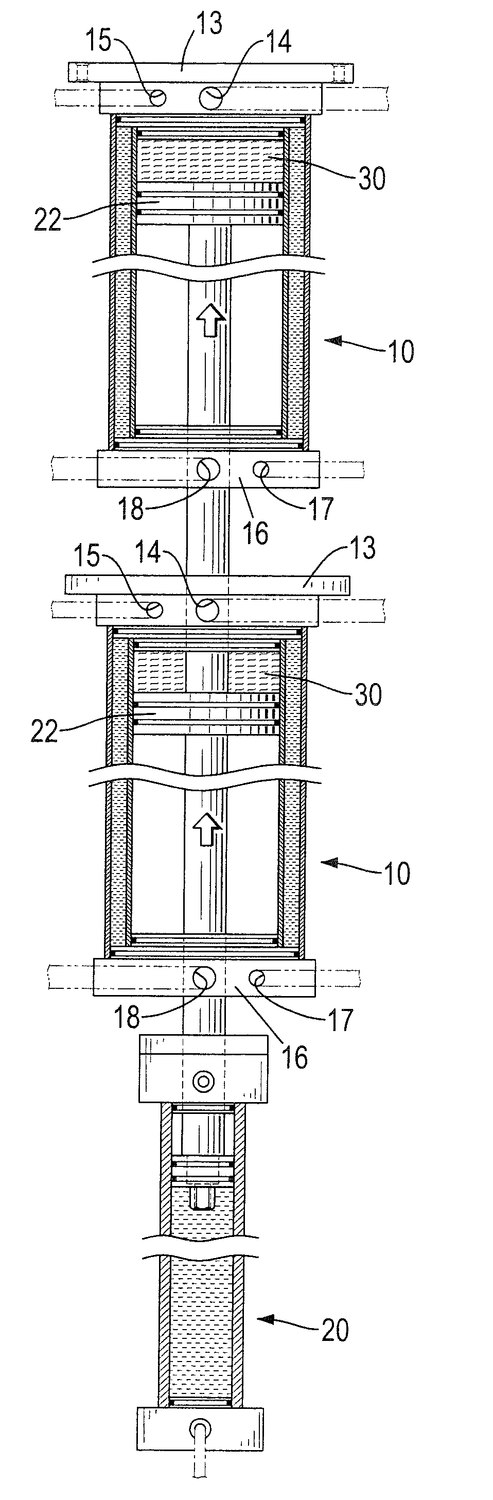
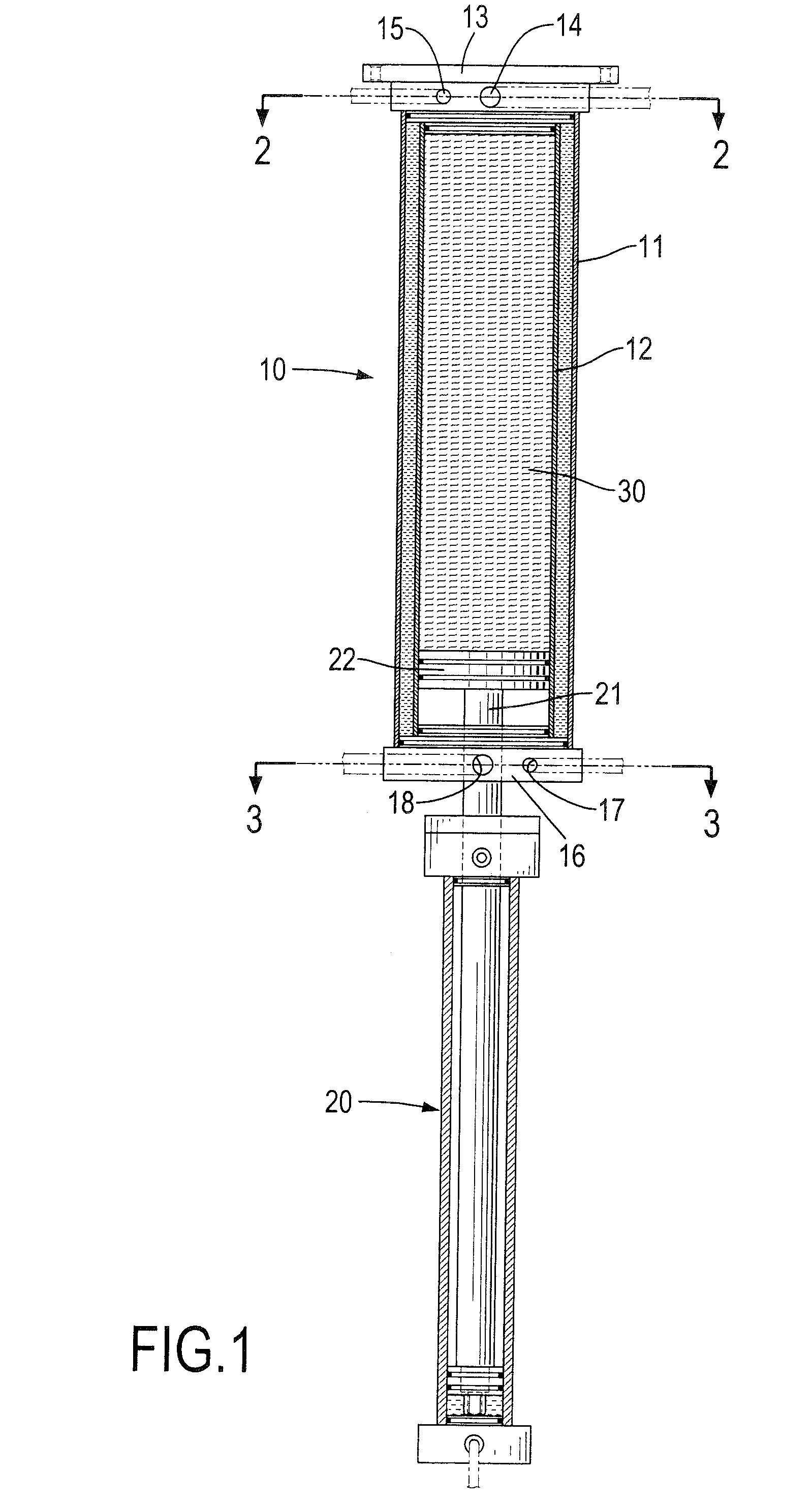
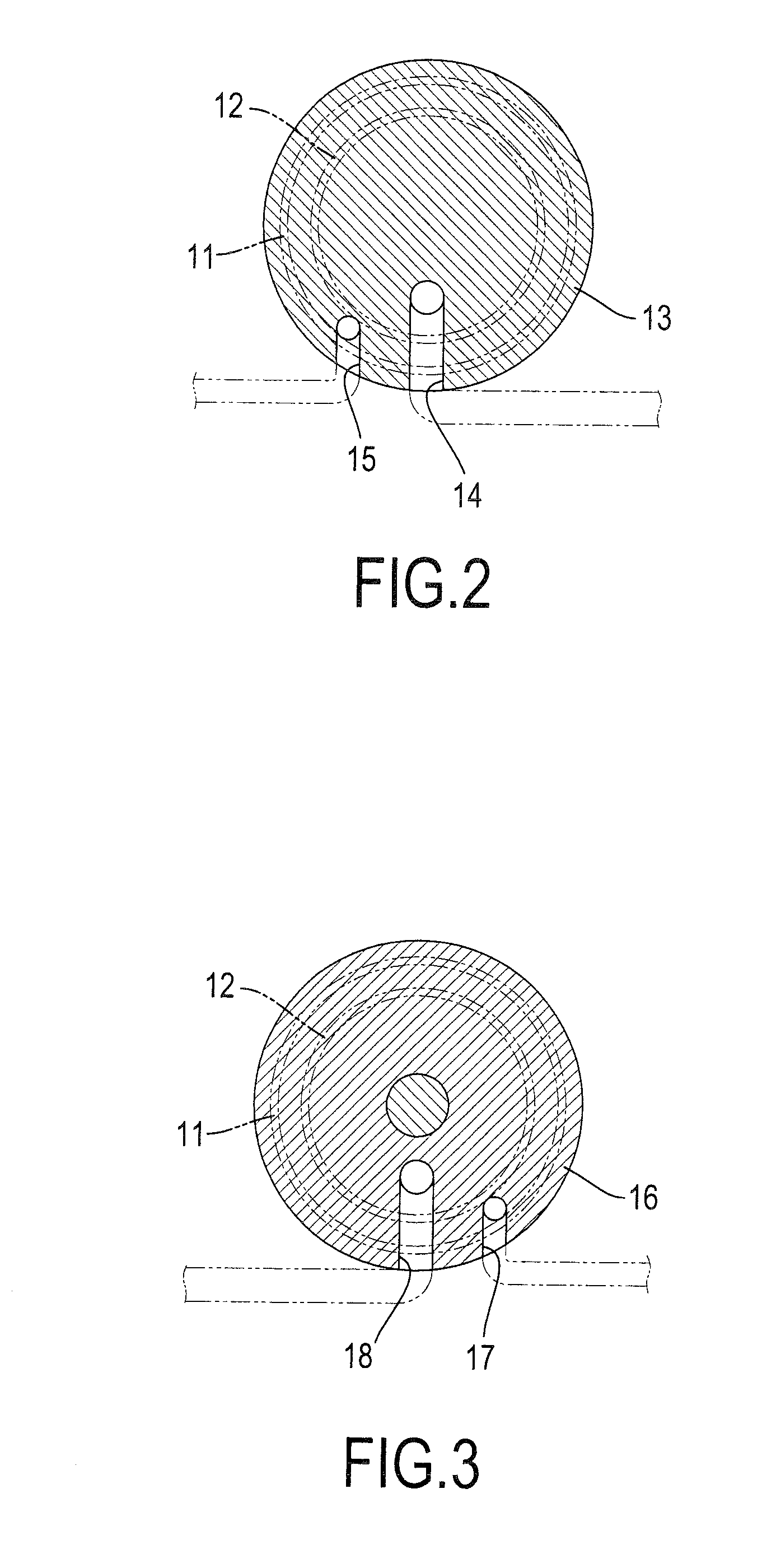
[0016]With reference to FIGS. 1, 2, 3 and 4, a feeding device for liquid materials in accordance with the present invention comprises a storage tank (10) and a hydraulic cylinder (20).

[0017]The storage tank (10) comprises an outer tube (11), an inner tube (12), a receiving space, a front cap (13) and a rear cap (16). The outer tube (11) is thermal conductive and has a front end and a rear end. The inner tube (12) is thermal conductive, is mounted coaxially in and spaced from the outer tube (11) and has a front end and a rear end. The receiving space is defined between the inner and outer tubes (11, 12).

[0018]The front cap (13) is mounted on the front ends of the inner and outer tubes (11, 12) and has a feeding inlet (14) and a front outlet (15). The feeding inlet (14) is defined in the front cap (13), communicates with the inner tube (12) and may be connected to a divider connected to a liquid material supply and a liquid material output through pipelines. The front outlet (15) is d...


PUM

PropertyMeasurementUnit
viscositiesaaaaaaaaaa
viscosityaaaaaaaaaa
thermal conductiveaaaaaaaaaa

Abstract

A feeding device for liquid raw materials includes a storage tank and a hydraulic cylinder. The storage tank includes an outer tube, an inner tube, a receiving space, a front cap and a rear cap. The inner tube is mounted coaxially in the outer tube. The receiving space is defined between the inner and outer tubes. The front cap is mounted on the inner and outer tubes and has a feeding inlet communicating with the inner tube and a front outlet communicating with the receiving space. The rear cap is mounted on the inner and outer tubes and has a rear inlet communicating with the receiving space. The hydraulic cylinder has a piston rod and a piston connected to the piston rod and mounted movably in the inner tube. Thus, the feeding device is simplified and quiet and can be used to transport materials of different viscosities.

Description

BACKGROUND OF THE INVENTION[0001]1. Field of Invention[0002]The present invention relates to a feeding device, and more particularly to a feeding device for liquid materials.[0003]2. Description of the Related Art[0004]A conventional feeding device may comprise a pump including a motor and a gear set or a diaphragm pump to feed liquid materials. However, the conventional mechanical or pneumatic pump may produce a great deal of noises and vibrations during operating. Thus, the conventional feeding device may cause unfavorable effects on field workers. Additionally, the mechanical pump includes many components like a rotor or bearings and has a complicated structure and a high manufacturing cost. Furthermore, the conventional mechanical and pneumatic pumps cannot feed different liquid materials in different viscosities and is limited in use.[0005]To overcome the shortcomings, the present invention provides a feeding device for liquid materials to mitigate or obviate the aforementioned...

Claims


Application Information

Patent Timeline
Patent Type & Authority Applications(United States)
IPC IPC(8): F04B19/22
CPCF04B9/10F04B23/023F04B9/113Y10T137/86187Y10T137/86324Y10T137/86035
Inventor LU, SHUN-TSUNG
Owner LU SHUN TSUNG
Why Eureka
Try Eureka