Reciprocating Tool

a reciprocating tool and tool body technology, applied in the field of reciprocating tools, can solve the problems of large resistance, insufficient vibration generation by the reciprocating motion of the working tool, and insufficient sliding of the first to third weight, so as to reduce the sliding resistance that develops as the weight moves with respect to the housing, reduce the vibration of the reciprocating tool sufficiently, and reduce the weight swing

Active Publication Date: 2010-02-18
HITACHI KOKI CO LTD
View PDF10 Cites 23 Cited by
  • Summary
  • Abstract
  • Description
  • Claims
  • Application Information

AI Technical Summary

Benefits of technology

[0011]With this structure, a sliding resistance generates only between the support member and the shaft, while the weight swings. Thus, the sliding resistance that develops as the weight moves with respect to the housing can be reduced. Accordingly, the weight can be swung sufficiently as a result of the vibration of the reciprocating tool generated by the reciprocating motion of the tool bit, thereby reducing t

Problems solved by technology

Inevitably, the sliding resistance is so large that the first to third weights cannot slide sufficiently.
Consequently, the vibration generated by the reciprocating motion of the working tool can hardly be reduce

Method used


Image

  • Reciprocating Tool
  • Reciprocating Tool
  • Reciprocating Tool

Examples


first embodiment

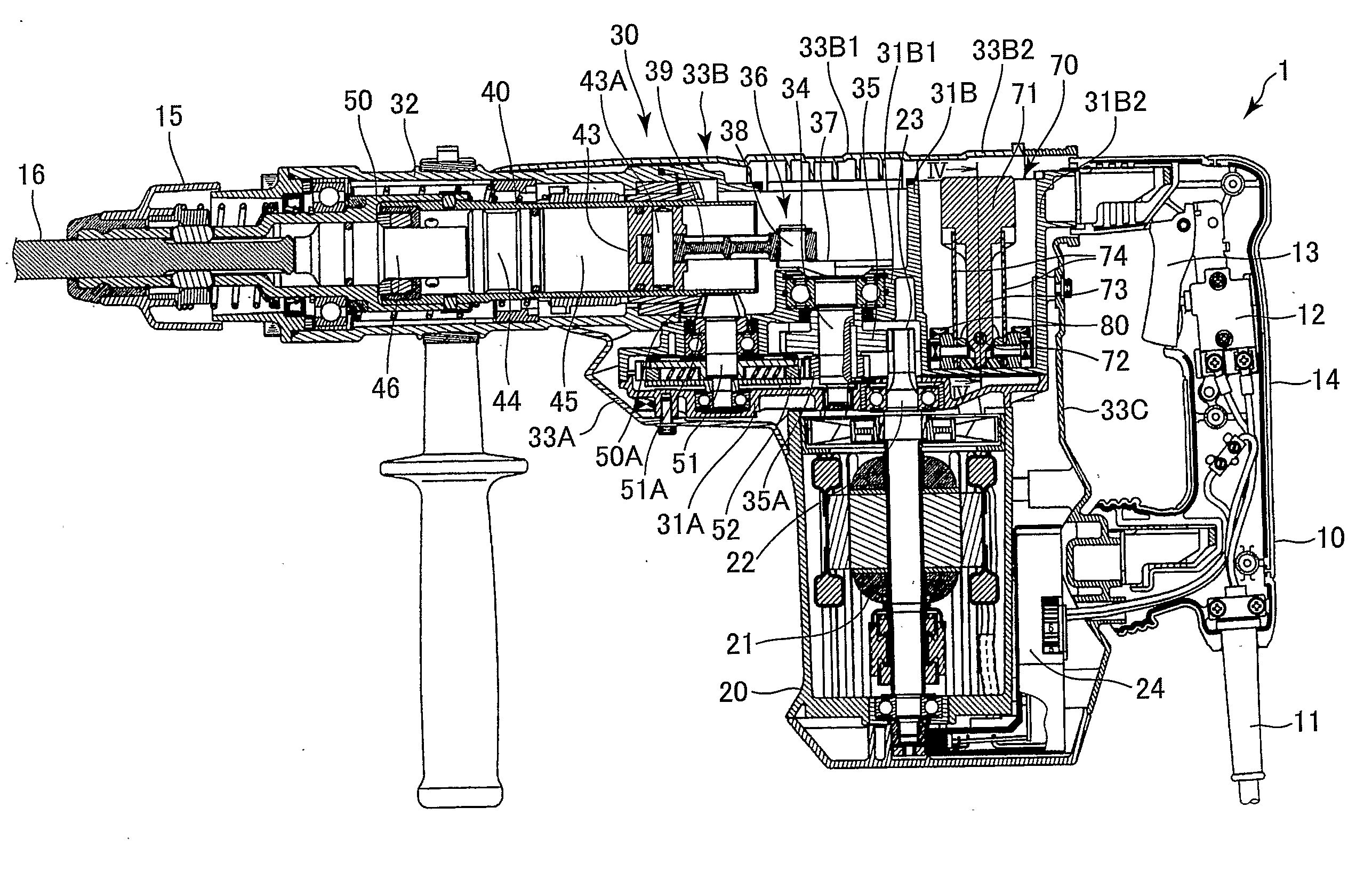
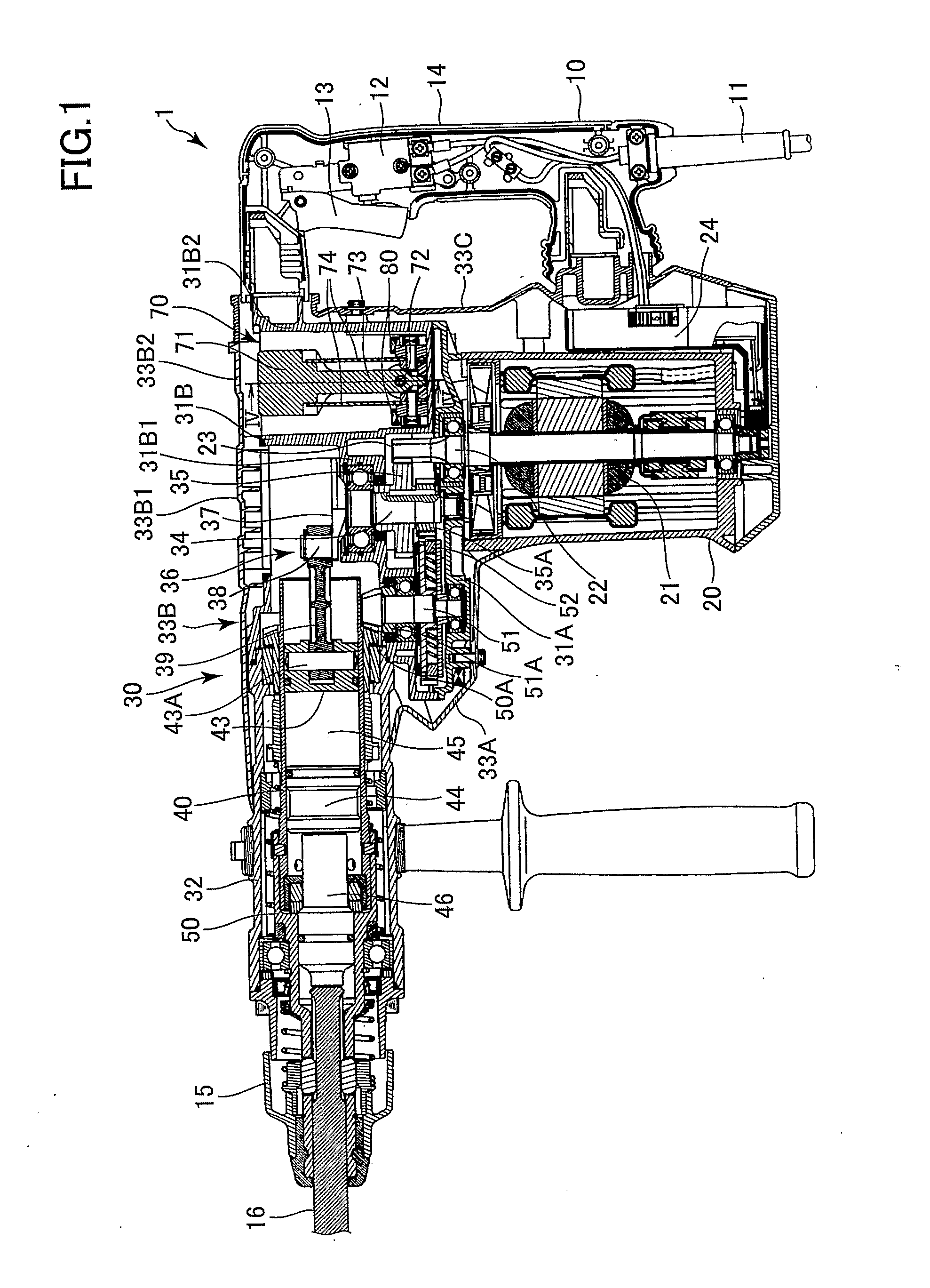
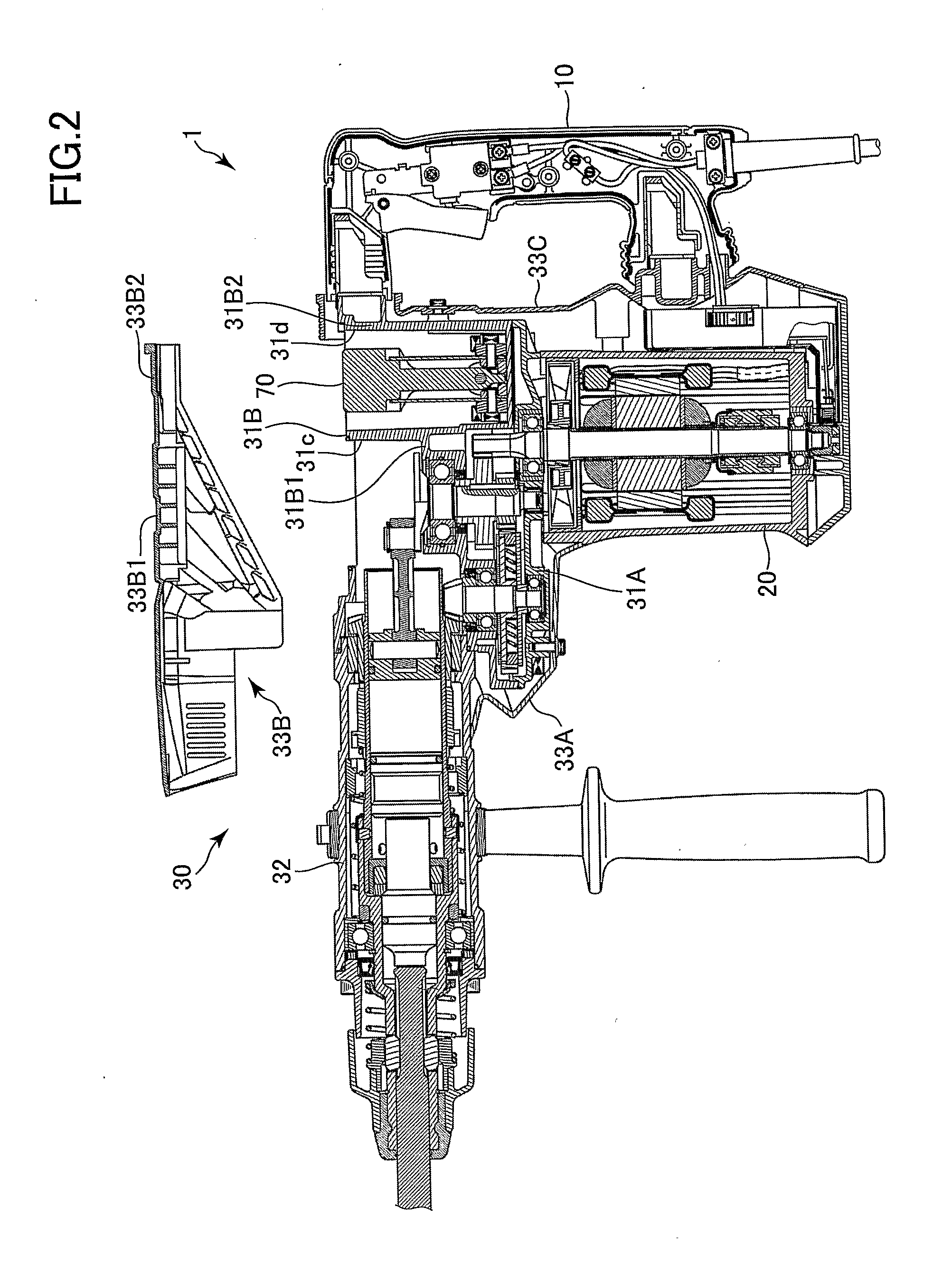
[0120]Next, the operation of the impact tool 1 will be described. The working tool 16 is pressed against a workpiece (not shown) with the handle 10 gripped by the user. Next, the trigger 13 is pulled to supply power to and rotate the electrical motor 21. This rotation driving force is transmitted to the crank shaft 34 by way of the pinion gear 23 and the first gear 35. The rotation of the crank shaft 34 is converted into reciprocating motion of the piston 43 in the cylinder 40 by the motion converter mechanism 36 (the crank weight 37, the crank pin 38, and the connecting rod 39). The reciprocating motion of the piston 43 leads to repeated increments and decrements the pressure of the air in the air chamber 45, thereby causing a reciprocating motion of the striking member 44. The striking member 44 moves forward and collides with the rear end of the intermediate member 46, thereby applying an impact force to the working tool 16.

[0121]Also, the rotation driving force of the electrica...

second embodiment

[0150]Further, in the second embodiment, instead of the pair of leaf springs 74, a pair of dampers may be provided on both ends of the weight 71 in the swing directions. The pair of dampers is made of resilient material and functions as swing-range restricting portion. With this structure, since each of dampers of the weight 71 abuts on a part of the storage section 31B2 which opposes the weight 71 in the swinging directions when the weight 71 swings by a second predetermined angle, the excessively swing (the swing range in the swing direction) of the weight 71 can be restricted reliably and easily. The second predetermined angle is the angle of the weight 71 and the support shaft 73 in which the damper of weight 71 abuts on the part of the storage section 31B2. Since the swing-range restricting portion is the pair of dampers, the impact force of the damper can be buffered when the damper strongly hits the storage section 31B2, thereby avoiding the breakage and deformation of the st...


PUM

PropertyMeasurementUnit
Massaaaaaaaaaa
Weightaaaaaaaaaa
Forceaaaaaaaaaa

Abstract

A reciprocating tool (1) includes a housing (20, 30), a driving source (21), a reciprocation conversion unit (34, 36), —and a vibration reduction mechanism (30). The driving source is accommodated in the” housing. The reciprocation conversion unit (34, 36) is supported by the housing and is configured to convert a driving force of the driving source into a reciprocating motion for providing a tool bit (16) movably supported to the housing with a reciprocating motion. The vibration reduction mechanism (70) includes a shaft (72), a weight (71), a support member (73), and a urging portion (74). The shaft i(72)s supported by the housing and extending in a direction perpendicular to directions of the reciprocating motion of the tool bit (41) t and has an axis. The weight (71) is located away from the shaft (72) and is swingable in a swinging direction. The support member (73) swingably supports the weight (71) about the axis of the shaft (72). The urging portion (74) urges the weight (71) toward a prescribed position of the weight in the swinging direction with respect to the housing.

Description

TECHNICAL FIELD[0001]The present invention relates to a reciprocating tool, more particularly, to a reciprocating tool that has a vibration reduction mechanism.BACKGROUND ART[0002]Reciprocating tools (electrical tools) that have a vibration reduction mechanism known as dynamic vibration absorber, have been proposed. The electric tool includes a housing, a working tool, a motor, a reciprocation conversion unit, and a striking mechanism. The working tool can reciprocate with respect to the housing. The motor, the reciprocation conversion unit, and the striking mechanism are provided in the housing. A handle is fixed to the back of the housing. A cylinder is provided on the lower part of the housing. The cylinder serves as vibration control chamber.[0003]In the vibration control chamber, a guide bar is provided. The guide bar extends parallel to the direction in which the working tool reciprocates. A first weight is mounted on the guide bar. The first weight is inserted into a first th...

Claims


Application Information

Patent Timeline
IPC IPC(8): B25D17/24
CPCB25D17/24B25D2217/0092F16F7/116B25D2250/245B25D2250/381B25D2250/121
Inventor KIKUCHI, ATSUYUKISUZUURA, TSUKASAHAGA, HIROSHIKANBE, KUNIAKIIKEDA, TOMOYA
Owner HITACHI KOKI CO LTD
Why Eureka
Try Eureka