Automotive construction machine

a construction machine and motor technology, applied in the direction of jet propulsion mounting, fluid couplings, separation processes, etc., can solve the problems of difficult maintenance and service work, difficult to keep the ureal water tank at a constant temperature level, and difficult to heat stably the entire urea solution in the tank

Inactive Publication Date: 2010-02-18
NIHON KENKI CO LTD
View PDF13 Cites 49 Cited by
  • Summary
  • Abstract
  • Description
  • Claims
  • Application Information

AI Technical Summary

Benefits of technology

[0009]In view of the above-discussed problem with the prior art, it is an object of the present invention to provide an automotive construction machine which is so arranged as to give a great degree of freedom with regard to the position of installation of a ureal water tank and to keep an aqueous urea solution in the tank stably in a heated state to prevent coagulation of the urea solution.

Problems solved by technology

Depending upon the position of a ureal water tank relative to nearby components, it may become difficult to carry out a maintenance and service work, for example, a job of refilling an aqueous urea solution into a ureal water tank.
Accordingly, depending upon a position of installation, it may become difficult to keep a ureal water tank at a constant temperature level.
In this case, temperature differences occur between different regions of the tank, making it difficult to heat stably the entire aqueous urea solution in the tank.

Method used


Image

  • Automotive construction machine
  • Automotive construction machine
  • Automotive construction machine

Examples


first embodiment

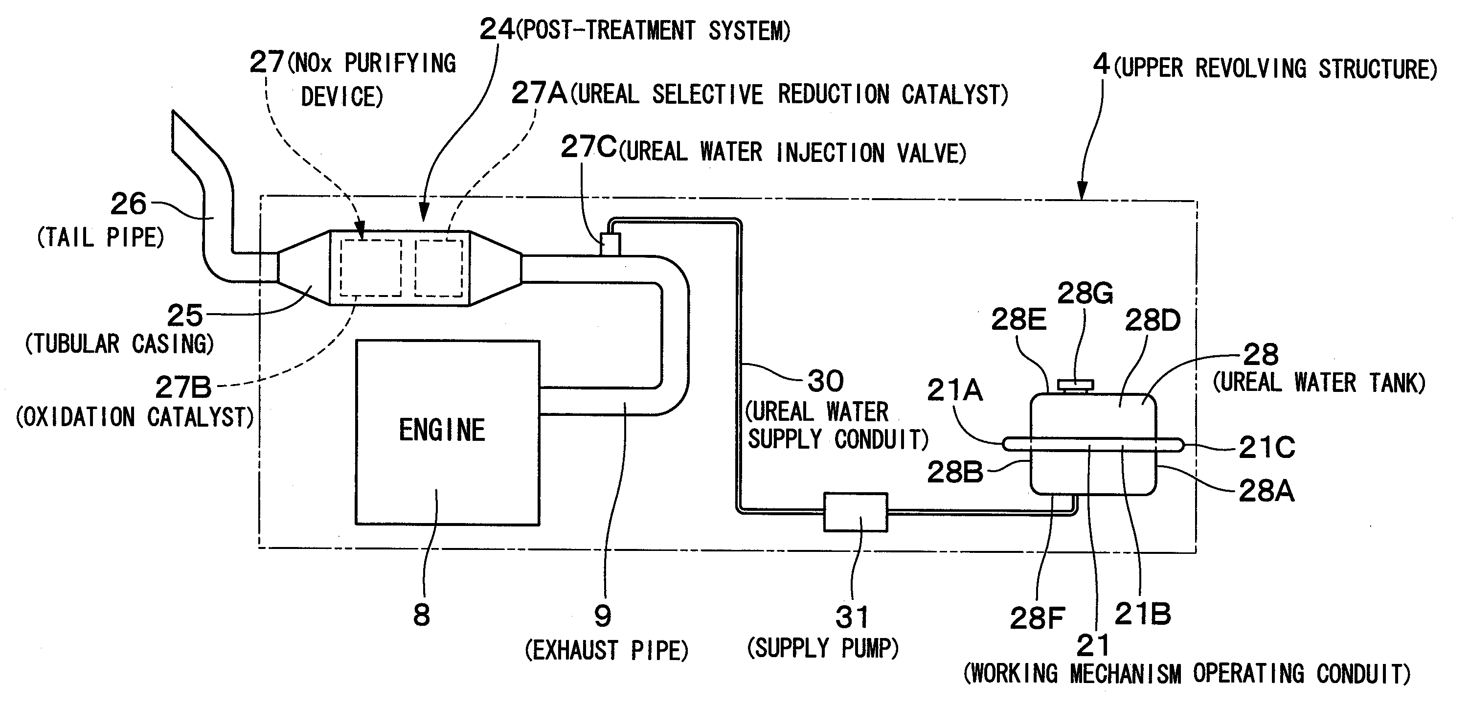
[0062]Now, described below by way of example is a first embodiment in which, among various working mechanism operating conduits 21 to and from the actuators 5D, 5E and 5F, a working mechanism operating conduit 21 from one of the boom cylinders 5D is arranged around the ureal water tank 28.

[0063]Namely, in the first embodiment, the ureal water tank 28 is kept in a heated state to prevent coagulation of an aqueous urea solution by the use of one of working mechanism operating conduits 21 which is connected between the control valve 16 and one boom cylinder 5D for supplying and discharging operating oil to and from the latter. One end of this working mechanism operating conduit 21 is connected to the control valve 16, while the other end is connected to one boom cylinder 5D of the working mechanism 5. Further, one working mechanism operating conduits 21 of a pair of the working mechanism operating conduits 21 is folded in U-shape on its way along the ureal water tank 28 on a right fron...

second embodiment

[0094]Indicated at 47 is a ureal water tank which is adopted in the This ureal water tank 47 is located in a so-called utility room which is located between cab 7 and engine 8 (oil cooler 11) in an outmost (leftmost) side section which is readily accessible from outside at the time of refilling. The ureal water tank 47 is fixedly set in position, for example, on a mount frame 48, and connected to a ureal water injection valve 27C through a ureal water supply conduit 49 and a supply pump 50.

[0095]Substantially in the same way as the ureal water tank 28 in the foregoing first embodiment, a surface of the ureal water tank 47 is in the form of a closed hexahedral container including front side surface 47A, rear side surface 47B, left side surface 47C, right side surface 47D, upper side surface 47E and lower side surface 47F. A cap 47G is put on the upper side surface 47E of the tank 47. The ureal water tank 47 is folded by the front conduit section 45C of the oil cooler side return con...

third embodiment

[0104]Further, in the third embodiment, by way of example, one of two working mechanism operating conduits 54, which are connected between the control valve 16 and boom cylinders 5D, is arranged to run along an upper side surface 57E of the ureal water tank 57, while the other working mechanism operating conduit 54 is arranged to run along a lower side surface 57F of the ureal water tank 57. However, the present invention is not limited to this particular example shown. For instance, as in a second modification of FIG. 12, there may be employed four working mechanism operating conduits 54 to run along exterior surface of the ureal water tank 57 in total, routing two working mechanism operating conduits 54 to run along an upper side surface 57E of a ureal water tank 57, while routing the other two working mechanism operating conduits 54 to run along a lower side surface 57F of the ureal water tank 57.

[0105]Now, turning to FIG. 13, there is shown a fourth embodiment of the automotive ...


PUM


Abstract

A ureal water tank (28), a storage of an aqueous urea solution, is located within a utility room (6G) in a right front section of a revolving frame (6), which is readily accessible from outside. In this instance, among a plurality of operating oil conduits (18), a working mechanism operating conduit (21) which supplies operating oil to a boom cylinder (5D) of a working mechanism (5) is arranged to run along exterior surfaces of the ureal water tank (28). Therefore, even if the ureal water tank (28) is located in a place with no heat source, the aqueous urea solution in the ureal water tank (28) can be stably kept in a heated state by utilization of heat of operating oil in circulation through the working mechanism operating conduit (21).

Description

TECHNICAL FIELD[0001]This invention relates to automotive construction machines such as, for example, hydraulic excavators, hydraulic cranes and wheel loaders, and more particularly to an automotive construction machine incorporating a urea selective reduction catalyst and ureal water tank in an upper revolving structure for the purpose of getting rid of emissions of nitrogen oxides in engine exhaust gases.BACKGROUND ART[0002]Generally, a hydraulic excavator, typical of automotive construction machines, is largely constituted by a vehicular lower structure which can be driven by a vehicle drive motor, an upper revolving structure swingably mounted on the vehicular lower structure for back and forth revolving motions, and a working mechanism liftably supported at the front of the upper revolving structure. An engine is mounted on the rear portion of a revolving frame on the upper revolving structure for the purpose of driving a hydraulic pump, while a cab, fuel tank and operating oil...

Claims


Application Information

Patent Timeline
Patent Type & Authority Applications(United States)
IPC IPC(8): B60K5/08F01N3/10F15B21/00
CPCB01D53/86B01D53/9431B01D2258/012B01D2259/4566E02F9/00E02F9/0808F15B21/06F01N3/2066F01N2610/02F01N2610/10F01N2610/1406Y02T10/24E02F9/0883Y02T10/12Y02A50/20B01D53/94F01N3/08F01N3/28
Inventor KAMIYA, SHOHEIARAI, YASUSHINAKAMURA, KAZUNORI
Owner NIHON KENKI CO LTD
Why Eureka
Try Eureka