Inductive soldering device

Inactive Publication Date: 2010-02-18
KOMAX HOLDING
View PDF8 Cites 23 Cited by
  • Summary
  • Abstract
  • Description
  • Claims
  • Application Information

AI Technical Summary

Benefits of technology

[0011]Another advantage of the present invention is that it reduces the influence of the different thermal expansions of the silicon solar cells and the flat wires. This is

Problems solved by technology

This means that a significant amount of the heat generated has to flo

Method used


Image

  • Inductive soldering device
  • Inductive soldering device
  • Inductive soldering device

Examples


Embodiment Construction

[0027]The U.S. provisional patent application Ser. No. 61 / 038,161, filed Mar. 20, 2008, and the U.S. patent application Ser. No. 12 / 408,054, filed Mar. 20, 2009, are hereby incorporated herein by reference.

[0028]The following detailed description and appended drawings describe and illustrate various exemplary embodiments of the invention. The description and drawings serve to enable one skilled in the art to make and use the invention, and are not intended to limit the scope of the invention in any manner. In respect of the methods disclosed, the steps presented are exemplary in nature, and thus, the order of the steps is not necessary or critical.

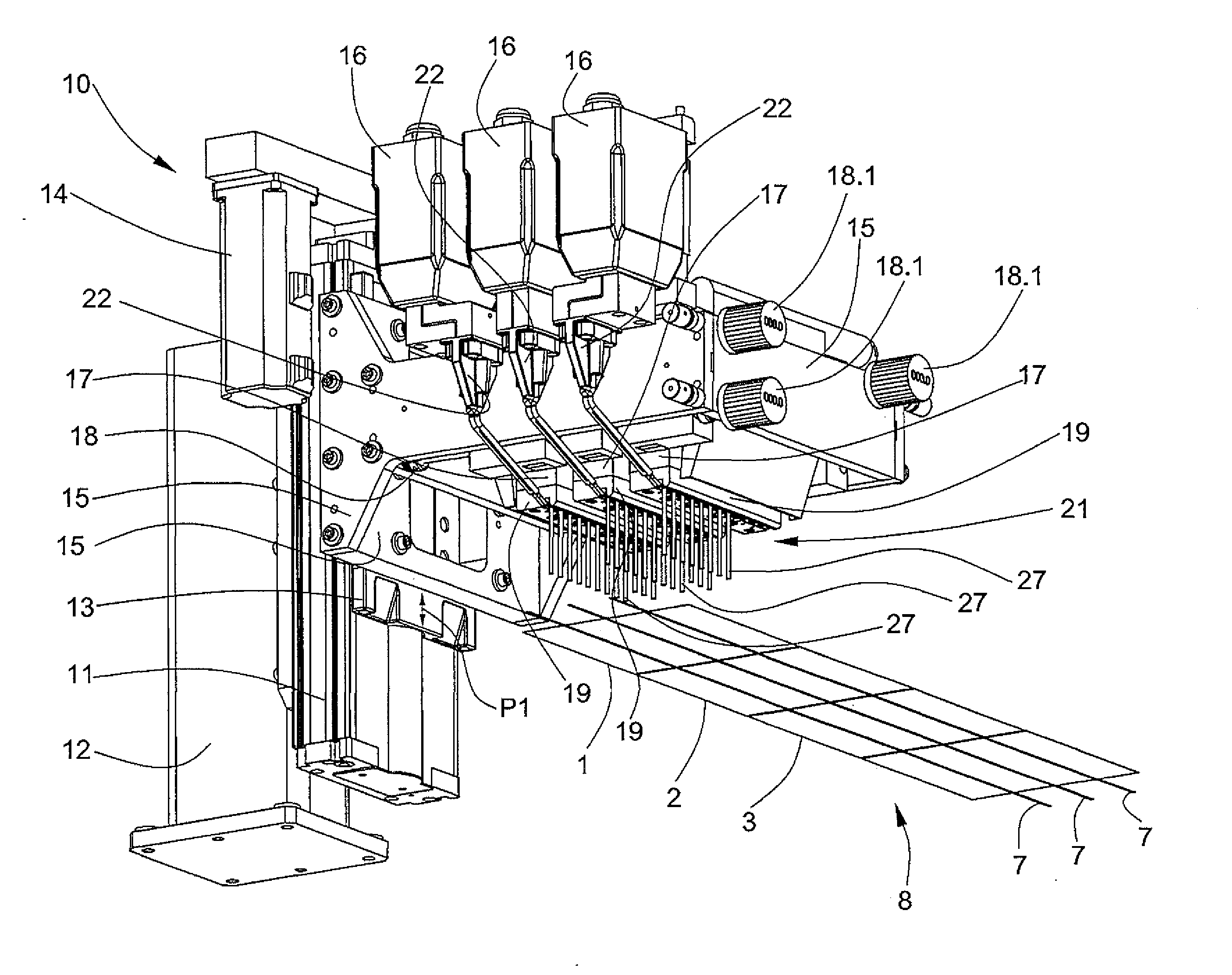
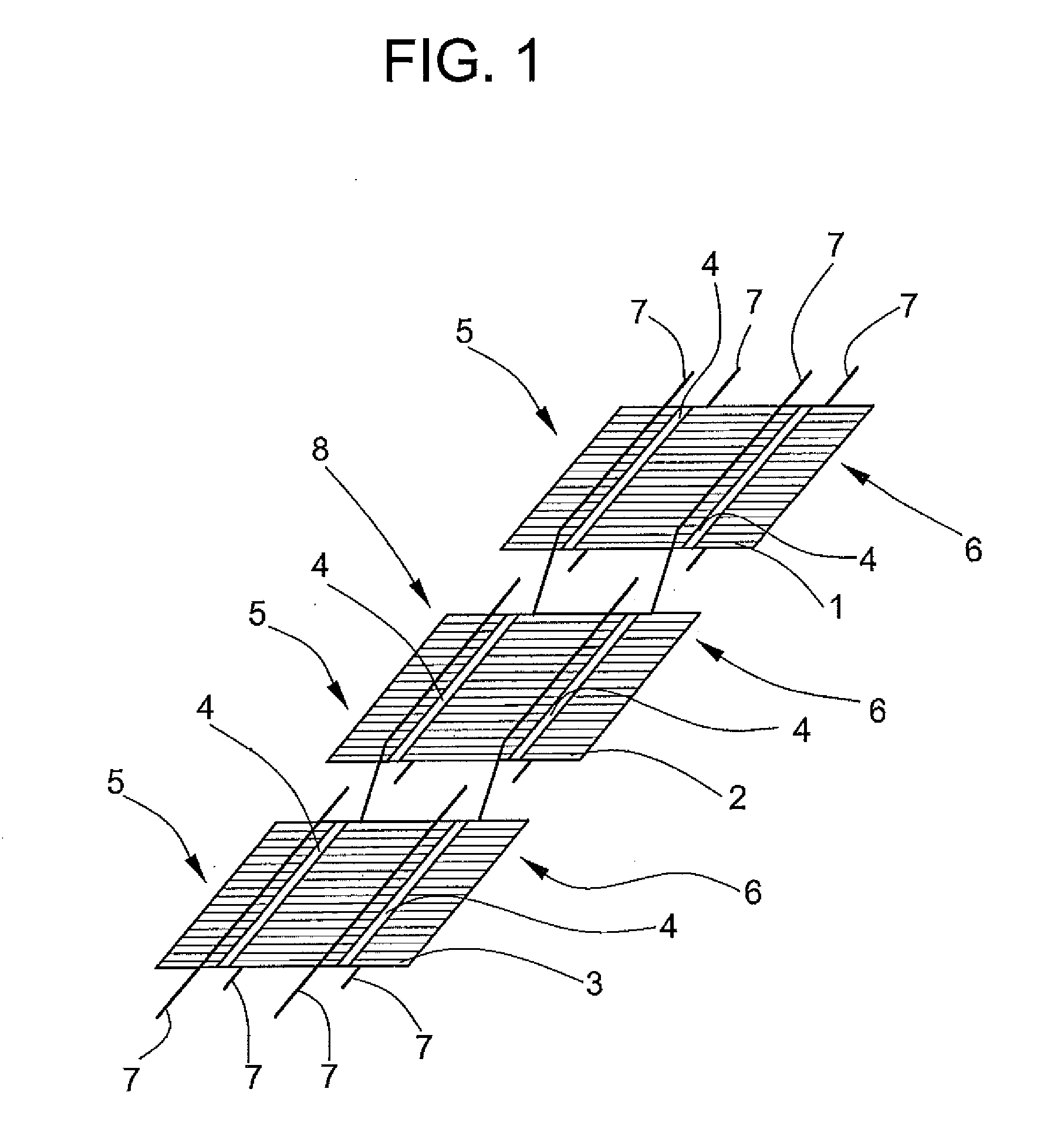
[0029]FIG. 1 shows a first solar cell 1, a second solar cell 2, and a third solar cell 3. The solar cells 1, 2, 3 are also referred to as photovoltaic cells and convert the radiant energy contained in light into electrical energy. The voltage that is generated in the individual cells prevails between conducting tracks 4 of the cell upper s...


PUM

PropertyMeasurementUnit
Angleaaaaaaaaaa
Magnetic fieldaaaaaaaaaa
Electrical currentaaaaaaaaaa

Abstract

A soldering apparatus for connecting solar cells includes an induction heat source to connect cell conducting tracks, provided with soldering medium, with electric conductors. The heat source has a high-frequency generator and an inductor loop in which the flow of a high-frequency current causes a high-frequency magnetic field to induce in the conducting track and in the electric conductor arranged along the conducting track eddy currents that generate the heat that is necessary for the soldering operation. The inductor loop includes a U-shaped loop element that has narrowings and widening in one arm that is positioned closer to the conductor. Ferrite beads and ferrite tubes at the widening concentrate the magnetic field to optimize the heat development in the soldering zone and thus also save energy.

Description

CROSS-REFERENCE TO RELATED APPLICATION[0001]This application is a continuation-in-part of U.S. patent application Ser. No. 12 / 408,054, filed Mar. 20, 2009, which claims the benefit of U.S. provisional patent application Ser. No. 61 / 038,161 filed Mar. 20, 2008.FIELD OF THE INVENTION[0002]The invention relates to an inductive soldering device used to generate heat for the soldering process to connect silicon solar cells with flat copper wires.BACKGROUND OF THE INVENTION[0003]From Production of crystalline photovoltaic modules is done by electrically connecting groups of silicon solar cells. Typically, individual cells are connected by flat copper wires (ribbons) into electrical series arrangements known as strings. The cell to cell stringing connections are ordinarily done using a soldering process to attach the flat copper wires to the front and back surfaces of the cells.[0004]A general concept of a method and apparatus for forming a solar cell string by inductive soldering is discl...

Claims


Application Information

Patent Timeline
IPC IPC(8): B23K1/002
CPCB23K1/0008B23K1/0016B23K1/002B23K3/0475Y02E10/50B23K3/085B23K2201/40H01L31/188B23K3/08B23K2101/40
Inventor DINGLE, BRAD M.MICCICHE, BRIAN S.SIDELINGER, SHAWN M.NEIDERT, KENNETH A.MEISSER, CLAUDIO
Owner KOMAX HOLDING
Why Eureka
Try Eureka