Voltage compensation circuit

a voltage compensation circuit and circuit technology, applied in the direction of circuit-breaking switches, circuit-breaking switches for excess current, circuit-breaking switch details, etc., can solve the problems of many electrical devices being damaged, and achieve the effect of greater winding thickness

Inactive Publication Date: 2010-02-18
TECH RES
View PDF3 Cites 27 Cited by
  • Summary
  • Abstract
  • Description
  • Claims
  • Application Information

AI Technical Summary

Benefits of technology

[0035]In a more specific embodiment of the invention, the first autotransformer winding has a majority of winding whereas the second autotransformer winding has a minority of windings.
[0036]In a more specific embodiment of the invention, the first position of the switch connects the first transformer winding as a primary winding and the second transformer winding as a secondary winding. The second position of the switch connects the second transformer winding as a primary winding and the first transformer winding as a shorted secondary winding. The first autotransformer winding has a greater number of windings than the second autotransformer winding. The first and second autotransformer windings have a ratio proportional to a desired elevated output AC voltage at the first and second output terminals. Preferably, the second autotransformer winding has a greater winding thickness than the second autotransformer winding. The first and second autotransformer windings have a ratio of thickness proportional to a ratio of the number of the first and the second autotransformer windings.
[0037]In another specific embodiment of the invention, the voltage compensation circuit includes a control for operating the switch in accordance with the input AC voltage between the first and second input terminals. Preferably, the control has a comparator for comparing the input AC voltage to a voltage reference. The switch comprises an electrically operated mechanical relay or a solid state relay for electrically switching between the first position and the second position in accordance with an output from the comparator. In one example, the control has a ground sensing circuit for sensing a proper grounding of the input AC voltage.

Problems solved by technology

It is well known in the art that many electrical devices may be damaged by a low voltage alternating current AC power input.

Method used


Image

  • Voltage compensation circuit
  • Voltage compensation circuit
  • Voltage compensation circuit

Examples


first embodiment

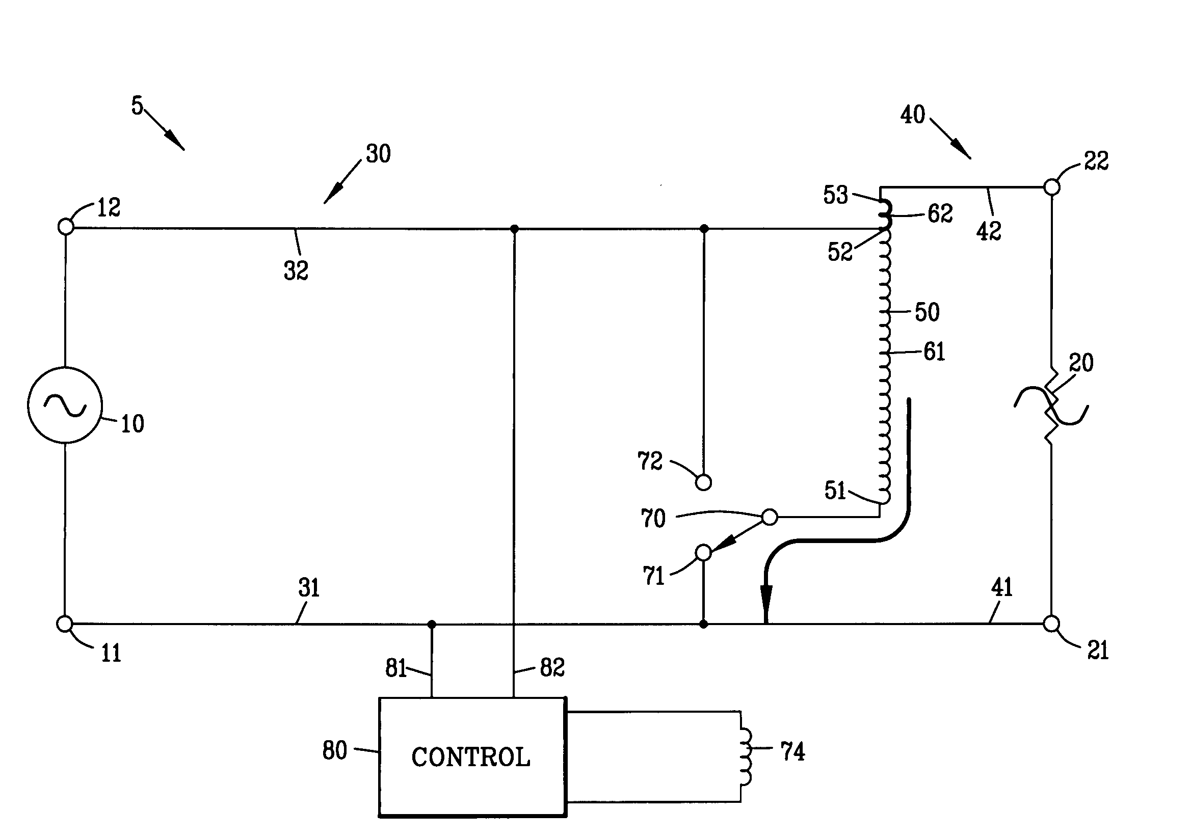
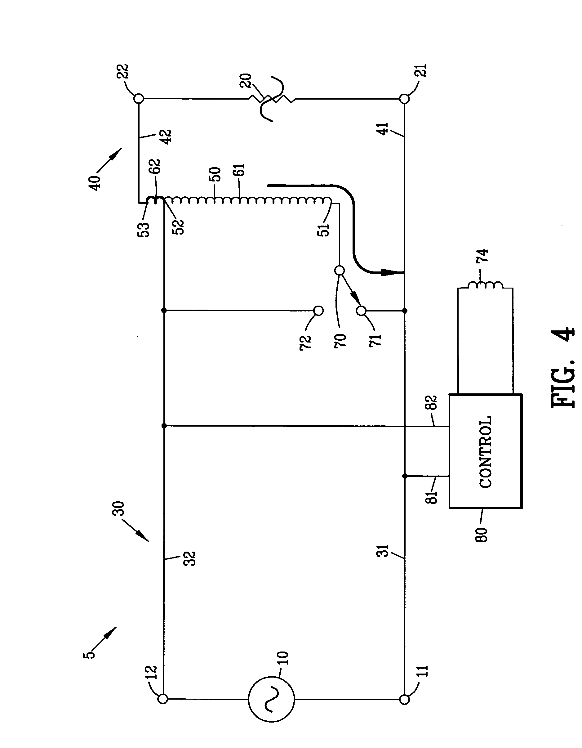
[0062]FIG. 4 is a circuit diagram of a voltage compensation circuit 5 of the present invention. The input AC voltage source 10 defines a first and a second input terminal 11 and 12. The input cable 30 comprises a first and a second input connector 31 and 32 whereas the output cable 40 comprises a first and a second output connector 41 and 42 for interconnecting the voltage compensation circuit 5 between the AC voltage source 10 and the load 20.

[0063]The voltage compensation circuit 5 comprises an autotransformer 50 having a first, second and a third transformer tap 51-53. The second transformer tap 52 of the autotransformer 50 is located between the first and third transformer taps 51 and 53. A first transformer winding 61 is defined between the first transformer tap 51 and the second transformer tap 52 of the autotransformer 50. A second transformer winding 62 is defined between the second transformer tap 52 and the third transformer tap 53 of the autotransformer 50.

[0064]In this e...

second embodiment

[0073]FIG. 6 is a circuit diagram of a voltage compensation circuit 105 of the present invention. Similar parts are labeled with similar reference characters raised by 100. In this example, the AC voltage source 110 is shown as a conventional 240-volt alternating current source. Although the AC voltage source 110 is shown as a conventional 240-volt AC voltage source, it should be understood that the AC voltage source 110 maybe any type of AC voltage source including one phase of a three phase electrical system.

[0074]The input AC voltage source 110 defines a first and a second input terminal 111 and 112 with a third input terminal 113 shown as a neutral terminal. The input cable 130 comprises first through third input connectors 131-133 whereas the output cable 140 comprises first through third output connector 141-143 for interconnecting the voltage compensation circuit 105 between the AC voltage source 110 and the load 120. In this example, the load 120 comprises a first and a seco...

third embodiment

[0092]Preferably, the voltage compensation circuit 205 is used for primarily regulating the voltage on the load 220C and secondarily for regulating the voltage on the loads 220A and 220B. The voltage compensation circuit 205 regulates the voltage on the loads 220A and 220B in accordance with the power requirement on the load 220C.

[0093]FIG. 10 is a circuit diagram of a fourth embodiment of a voltage compensation circuit 305 of the present invention. The fourth embodiment of the voltage compensation circuit 305 is a variation of the voltage compensation circuit 305 shown in FIGS. 8-9 with similar parts are labeled with similar reference characters raised by 100.

[0094]In this embodiment, the voltage compensation circuit 305 includes a single control 380. The control 380 sense an under voltage condition of the input AC voltage source between the first and the third terminals 311 and 313 and moves the switches 370A and 370B in unison into the first positions 371A and 371B. The under vol...


PUM


Abstract

A voltage compensation circuit is disclosed for proving an elevated output AC voltage upon an under voltage input AC voltage condition. The voltage compensation circuit comprises an autotransformer having a first and a second autotransformer winding. A first position of a switch connects the first autotransformer winding to the input AC voltage for providing an elevated output AC voltage at the second autotransformer winding. The second position of the switch shorting the first autotransformer winding for providing a non-elevated output AC voltage.

Description

CROSS-REFERENCE TO RELATED APPLICATIONS[0001]This application claims benefit of U.S. Patent Provisional application No. 61 / 189,170 filed Aug. 15, 2008. All subject matter set forth in provisional application 61 / 189,170 filed Aug. 15, 2008 is hereby incorporated by reference into the present application as if fully set forth herein.BACKGROUND OF THE INVENTION[0002]1. Field of the Invention[0003]This invention relates to electrical power circuit and more particularly to a voltage compensation circuit for proving an elevated output AC voltage upon an undervolt input AC voltage condition.[0004]2. Description of the Related Art[0005]It is well known in the art that many electrical devices may be damaged by a low voltage alternating current AC power input. Among the electrical devices that are most sensitive to a low voltage input include electric motors that power various devices such as an air conditioning compressor.[0006]Various devices have been proposed by the prior art to compensat...

Claims


Application Information

Patent Timeline
Patent Type & Authority Applications(United States)
IPC IPC(8): G05F5/04H01H73/18
CPCH02M5/12
Inventor SYKES, DAVID L.
Owner TECH RES
Why Eureka
Try Eureka