
Hearing Aid Device with a Transducer Protection Facility

a technology of transducer protection and hearing aid, which is applied in the direction of hearing aid vents, deaf-aid sets, electric devices, etc., can solve the problems of total failure of the affected hearing aid device, acoustic impairment, and aid devices which can be worn in the ear, and achieve the effect of ensuring the intended function of the pressure equalization channel

Active Publication Date: 2010-02-18
SIVANTOS PTE LTD
View PDF9 Cites 47 Cited by
  • Summary
  • Abstract
  • Description
  • Claims
  • Application Information

AI Technical Summary

Benefits of technology

[0010]The object of the present invention is therefore to easily ensure the intended function of the pressure equalization channel in the case of a hearing aid device with a transducer protection facility and a pressure equalization channel.
[0015]The transducer protection facility can be used both to protect one or several microphones in an inventive hearing aid device as well as to protect the receiver against dirt, in particular cerumen, moisture etc.
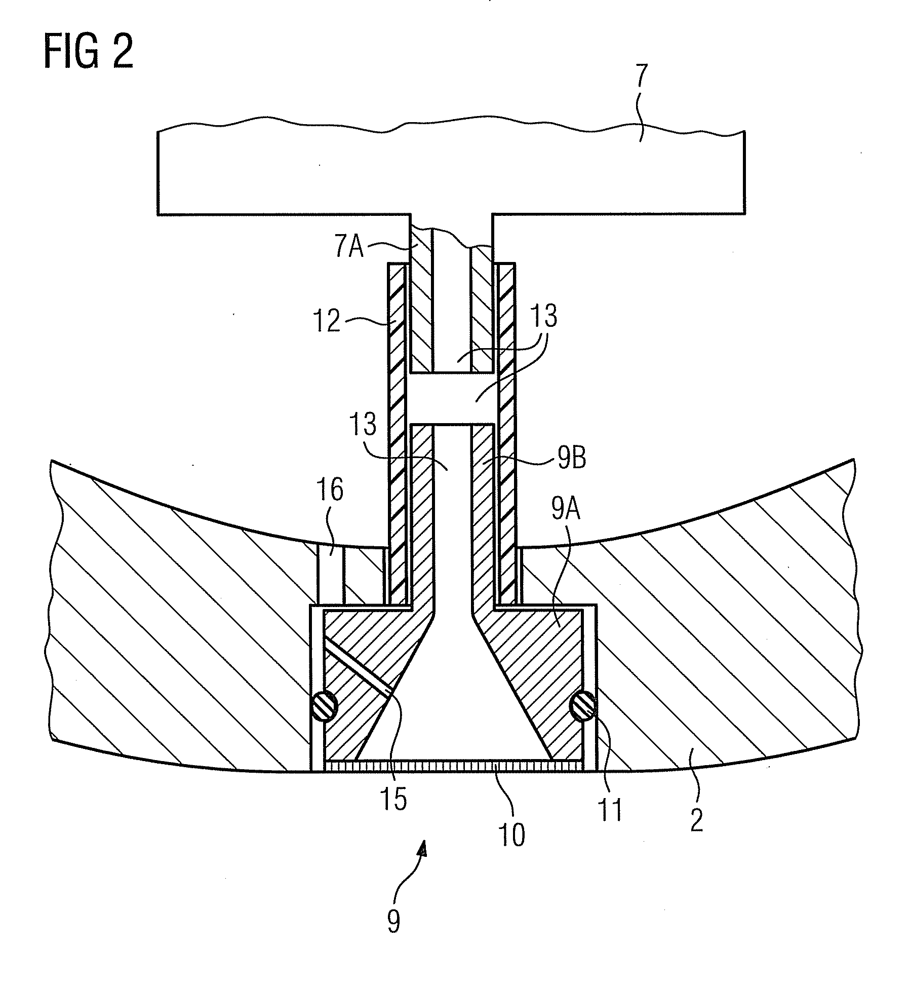
[0016]As in the case of the hearing aid device known from the patent application DE 10 2006 008 044 B3, in the hearing aid device according to the invention the membrane of the transducer protection facility also prevents the penetration of dirt or moisture into the pressure equalization channel. However in the rare instances when the pressure equalization channel becomes blocked, for example as a result of a damaged membrane in the transducer protection facility, the invention is advantageous in that at least one section of the pressure equalization channel can be replaced together with the transducer protection facility. Thus the transducer protection facility is in any case replaced from time to time as a part that is subject to wear and tear. The risk of blockage of the pressure equalization channel is significantly reduced and / or a blocked pressure equalization channel is easily replaced by a new, unblocked pressure equalization channel.
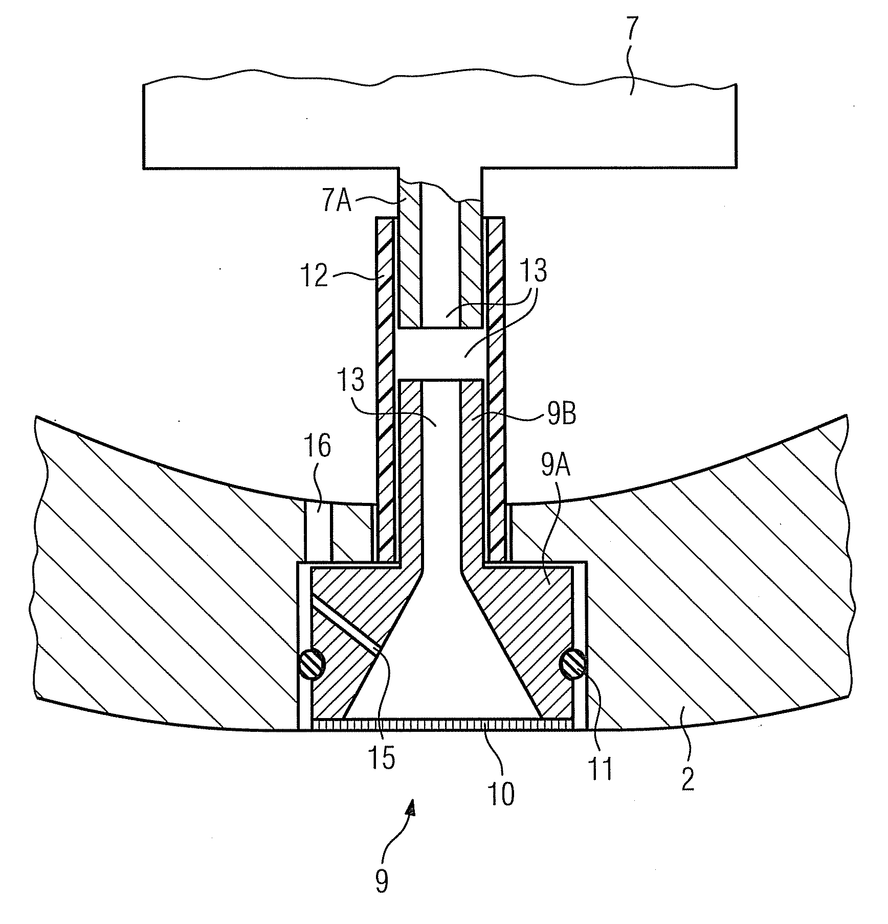
[0017]One advantageous embodiment of the invention provides for the pressure equalization channel to be subdivided into at least two subsections, with the first subsection extending through the transducer protection facility and the second subsection extending through the housing or the otoplastic of the relevant hearing aid device, as a result of which a continuous channel is created between the sound channel and the interior of the relevant hearing aid device and / or otoplastic. The section of the pressure equalization channel which extends through the transducer protection facility and which can therefore be easily replaced advantageously has a smaller cross-section than the section of the pressure equalization channel which extends through the housing and / or the otoplastic of the hearing aid device. This thus ensures that as a result of a damaged membrane in the transducer protection facility for instance, penetrating dirt particles already cling to the first section of the pressure equalization channel and therefore after the damaged transducer protection facility has been replaced, the intended function of the pressure equalization channel is fully ensured again.

Problems solved by technology

Hearing aid devices, in particular hearing aid devices which can be worn in the ear (ITE) are exposed to contamination with ear wax (cerumen).
This causes a number of problems, ranging from acoustic impairments to the total failure of the affected hearing aid device.
Cleaning of such cerumen protection facilities represents a significant problem.
In many instances the cerumen protection facility has to be replaced from time to time, which means that elderly hearing aid device wearers have to visit the acoustician, which is often problematic.
Attachable cerumen protection facilities have ultimately not been successful because of the additional space requirement.
The insertable cerumen protection facilities used to date are in most cases disadvantageous in that they reduce the acoustically active cross-section of the sound channel and may as a result lead to acoustic disadvantages.
However in the rare instances when the pressure equalization channel is blocked, cleaning is difficult.

Method used


Image

  • Hearing Aid Device with a Transducer Protection Facility
  • Hearing Aid Device with a Transducer Protection Facility
  • Hearing Aid Device with a Transducer Protection Facility

Examples


Embodiment Construction

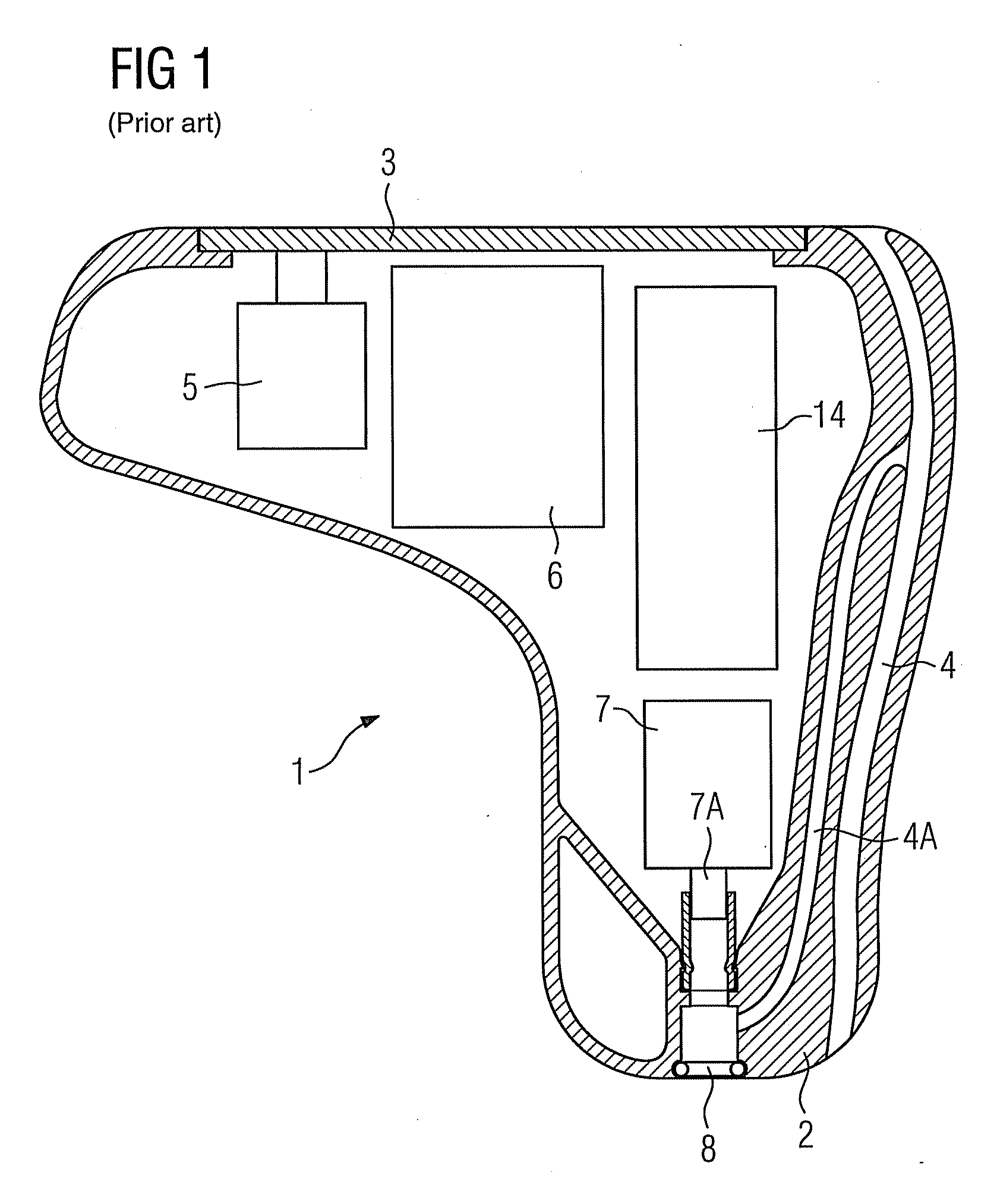
[0025]FIG. 1 shows a hearing aid device 1 which can be worn in the ear and is known from the prior art, comprising a housing 2, which, when the hearing aid device is being worn, has a first housing region facing the eardrum of a user and a second housing region facing away from the ear drum. The latter is usually referred to as a faceplate 3. The hearing aid device 1 is crossed between the first and the second housing region by a ventilation channel 4 for ventilating the auditory canal volume enclosed by the hearing aid device 1 when in the worn state. At least one microphone 5 for receiving an acoustic input signal and converting said signal into an electrical input signal, a signal processing unit 6 for the processing and frequency-dependent amplification of the electrical input signal and for generating an electrical output signal as well as a receiver 7 for converting the electrical output signal into an acoustic output signal, which is fed to the ear of the user by way of an ac...


PUM


Abstract

With a hearing aid device which can be worn in the ear, a barometric pressure equalization which is needed for the sound transducer, such as a microphone or receiver, is to be achieved in a simple and cost-effective fashion. To this end, a converter protection facility is proposed with a membrane, with a pressure equalization channel, which connects a sound channel to the interior of the hearing aid device, extends through the transducer protection facility at least in one section. Replacing the transducer protection facility thus also replaces this subsection of the pressure equalization channel. A possible blockage of the pressure equalization channel which exists in this region as a result of dirt or moisture is eliminated as a result.

Description

CROSS REFERENCE TO RELATED APPLICATIONS[0001]This application claims priority of German application No. 10 2008 038 213.2 filed Aug. 18, 2008, which is incorporated by reference herein in its entirety.FIELD OF THE INVENTION[0002]The invention relates to a hearing aid device comprising a housing, an input transducer for receiving an input signal and converting said signal into an electrical input signal, a signal processing unit for processing and amplifying the electrical input signal and for generating an electrical output signal, an output transducer for converting the electrical output signal into an output signal which can be perceived by a user as an acoustic signal and a transducer protection facility which can be detachably connected to the hearing aid device and has a membrane support, a membrane and a sound channel, for protecting the input transducer or the output transducer against contamination.BACKGROUND OF THE INVENTION[0003]Hearing aid devices, in particular hearing a...

Claims


Application Information

Patent Timeline
Patent Type & Authority Applications(United States)
IPC IPC(8): H04R25/00
CPCH04R2460/11H04R25/654B33Y80/00
Inventor GEBERT, ANTON
Owner SIVANTOS PTE LTD
Learn More