Axial fan casing design with circumferentially spaced wedges

a wedge wedge and axial fan technology, applied in the direction of machines/engines, manufacturing tools, liquid fuel engines, etc., can solve the problems of significant losses in axial flow fans, reduced performance, increased noise level, etc., to reduce the loss of clearance flow and increase stability.

Inactive Publication Date: 2010-02-18
CARRIER CORP
View PDF15 Cites 9 Cited by
  • Summary
  • Abstract
  • Description
  • Claims
  • Application Information

AI Technical Summary

Benefits of technology

[0007]Briefly, in accordance with one aspect of the invention, a sharp, forward facing step is provided in the fan casing and a plurality of circumferentially spaced wedges are included on the step of the casing wall to obtain both a restriction in clearance flow losses and increased stability.

Problems solved by technology

Significant losses occur in axial flow fans due to backflow in the clearance region between the fan rotor and the casing.
In either case backflow is driven from the high pressure side of the rotor to the suction side across the clearance gap, leading to reduced performance, increased noise level and reduced stability and stall-margin.
These flows tend to develop into organized rotating cells which can lead to strong through-flow oscillations and excessive noise.

Method used


Image

  • Axial fan casing design with circumferentially spaced wedges
  • Axial fan casing design with circumferentially spaced wedges
  • Axial fan casing design with circumferentially spaced wedges

Examples


Embodiment Construction

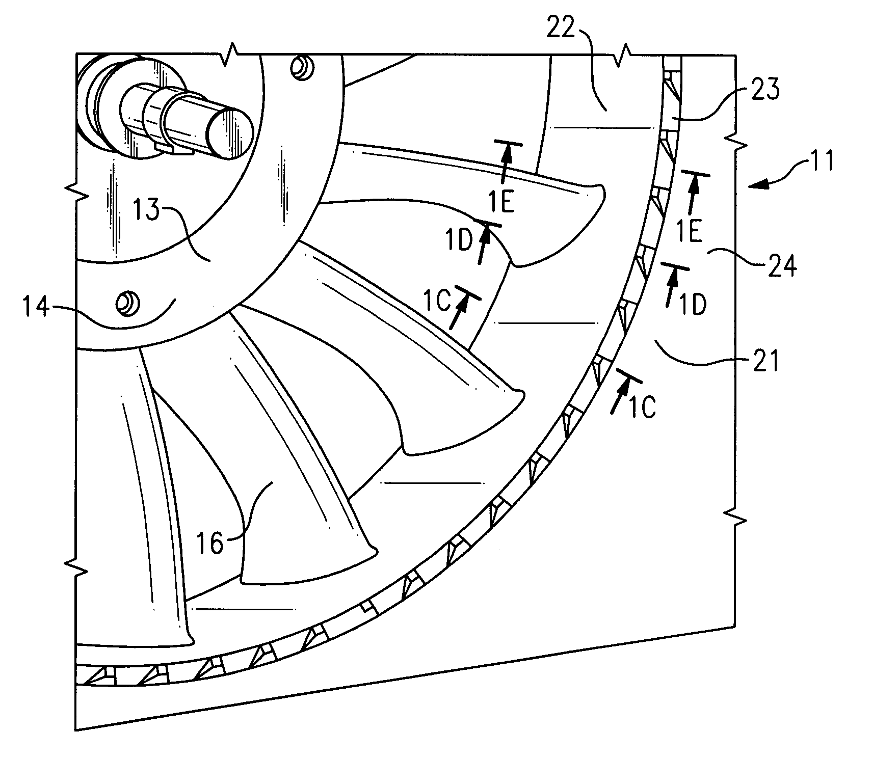
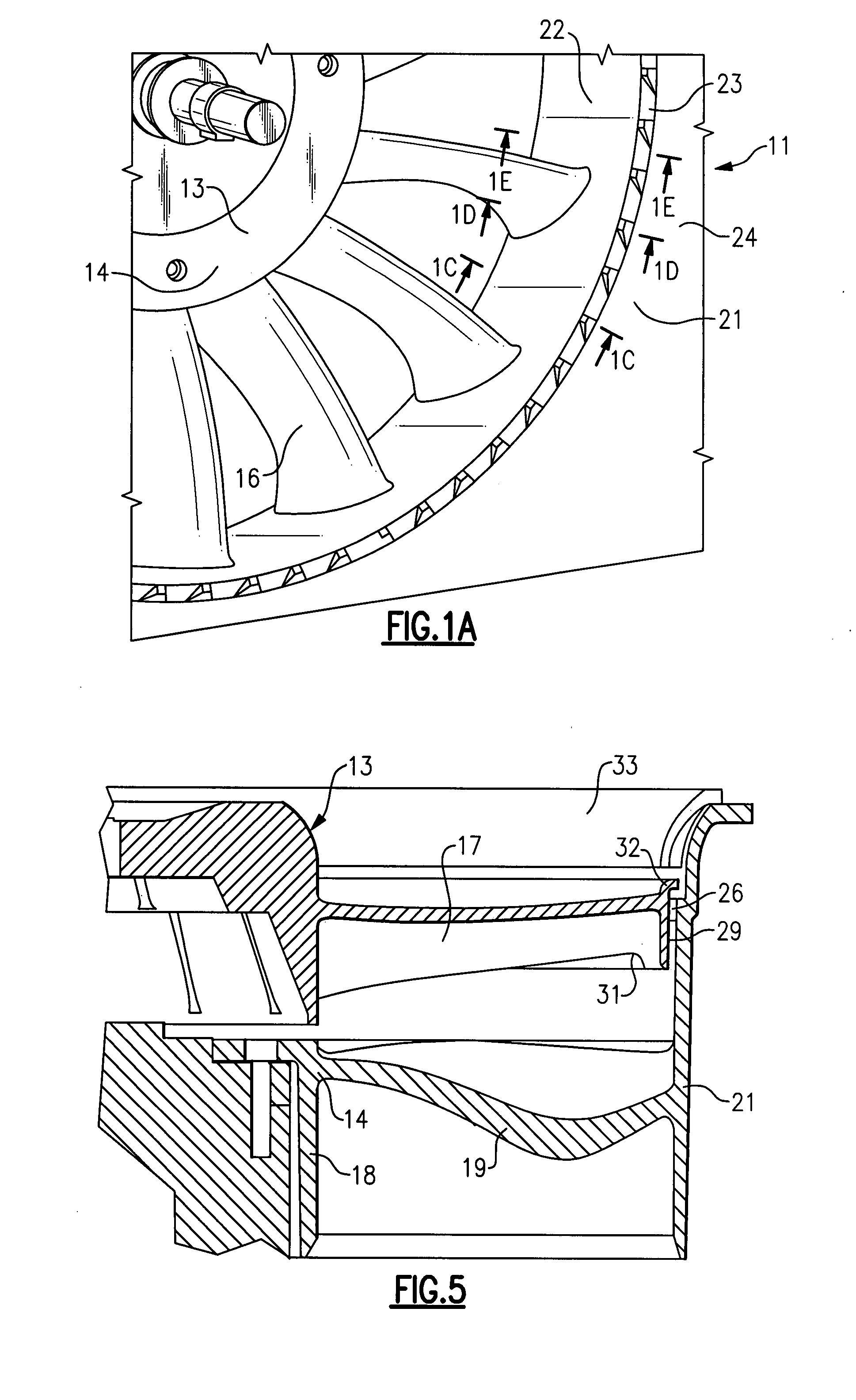
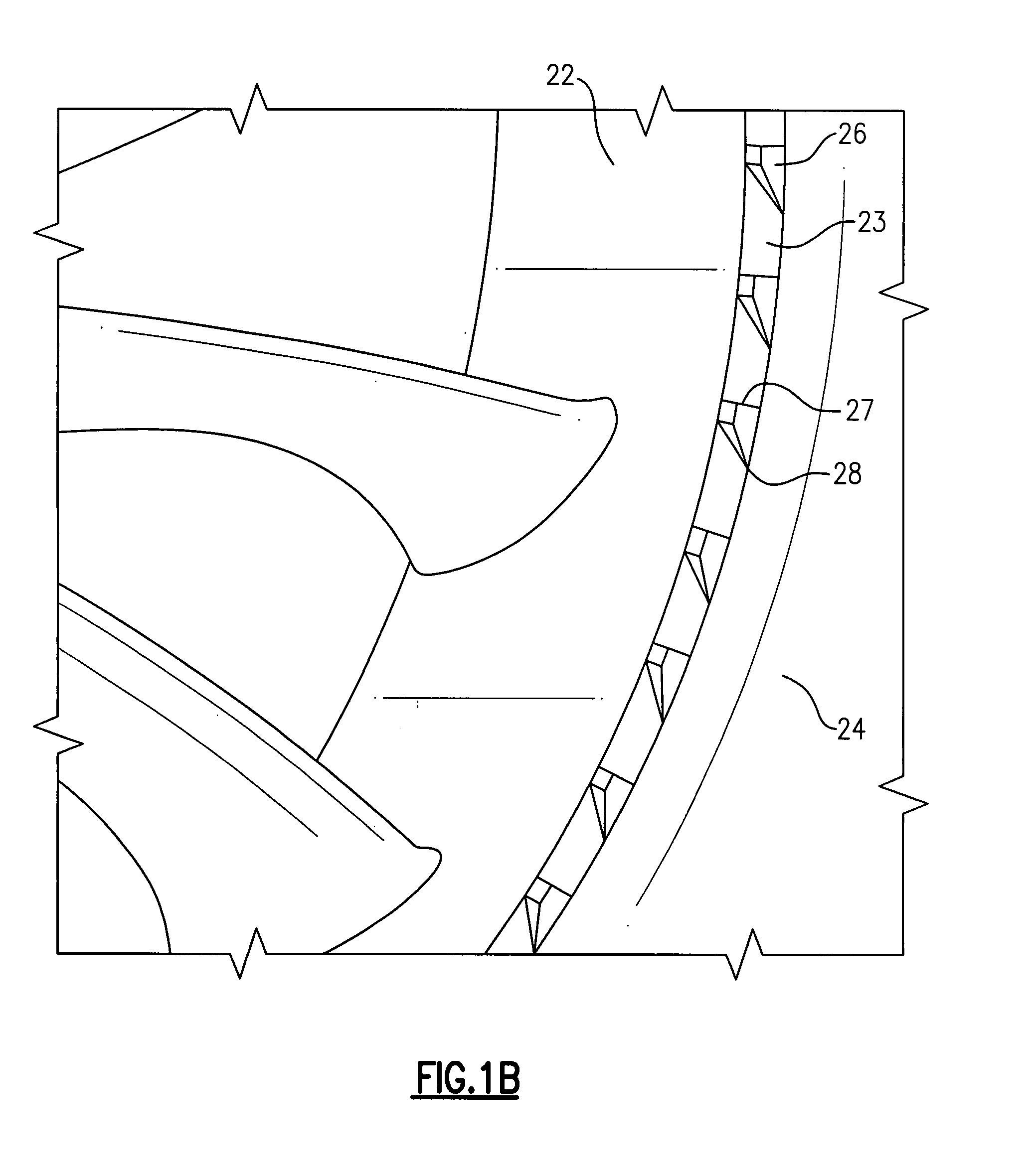
[0025]Referring now to FIGS. 1A thru 1E and 2A, the invention is shown generally at 11 as applied to an axial fan assembly that includes in serial airflow relationship, an axial fan 13 and a stator 14. The axial fan 13 includes a rotatable hub 16 and a plurality of fan blades 17. The stator 14 includes a stationary hub 18 and a plurality of radially extending stationary vanes 19 having their radially outer ends integrally connected to a cylindrical outer casing 21. In operation, the fan 13 is rotated at relatively high speeds to induce the flow of air through the casing 21, and in the process it creates a swirl in the direction of the fan rotation. The stator vanes 19 are so disposed and shaped so as to substantially remove the swirl from the main air flow stream such that the flow at the downstream end is substantially axial in direction.

[0026]As is well known in the art, the dimensions of the fan blade 17 are such that the radial clearance between the ends of the fan blades 17 and...


PUM

PropertyMeasurementUnit
dimensionaaaaaaaaaa
operational stabilityaaaaaaaaaa
noise levelaaaaaaaaaa

Abstract

An axial fan assembly including a casing wall with a forward facing step formed therein. Formed on the surface of the step is a plurality of circumferentially spaced wedges which are formed and positioned so as to reduce the swirl flow within the clearance gap between the fan rotor and casing. The wedges are formed so the swirling backflow first encounters a circumferentially tapered face and then an abrupt axially oriented face, thereby substantially removing the swirl component. The wedges have a favorable effect on the flow stability of the fan, thereby extending its operating range. Variations include a fan rotor with a rotating shroud with an outwardly extending portion overlapping the step, and a bellmouth piece at the casing inlet.

Description

BACKGROUND OF THE INVENTION[0001]This invention relates generally to axial flow fans and, more particularly, to a method and apparatus for reducing their clearance flow losses and improving their operational stability.[0002]Axial flow fans are used in a wide variety of applications, including HVAC, refrigeration, automotive, power systems and aerospace. In each of these applications, performance, noise level, operating range and compactness are important considerations.[0003]Significant losses occur in axial flow fans due to backflow in the clearance region between the fan rotor and the casing. The rotor may utilize conventional blades that extend outward with blade tips approaching the casing, or it may utilize blades that include a rotating shroud attached to the blade tips. In either case backflow is driven from the high pressure side of the rotor to the suction side across the clearance gap, leading to reduced performance, increased noise level and reduced stability and stall-ma...

Claims


Application Information

Patent Timeline
Patent Type & Authority Applications(United States)
IPC IPC(8): F01D11/08B23P11/00
CPCF04D29/164Y10T29/49245F04D29/526F04D29/685
Inventor BUSHNELL, PETER R.
Owner CARRIER CORP
Why Eureka
Try Eureka