

Film cooling structure
a cooling structure and film technology, applied in the direction of liquid fuel engines, machines/engines, mechanical equipment, etc., can solve the problems of difficult to improve ineffective diffusion, and achieve the effect of increasing the enlarged angle and improving the average film cooling efficiency
- Summary
- Abstract
- Description
- Claims
- Application Information
AI Technical Summary
Benefits of technology
Problems solved by technology
Method used
Image

Examples
Embodiment Construction
[0036]A preferred embodiment of the invention will be described in detail below with reference to accompanying drawings. Meanwhile, the same reference numerals are given to common portions in each drawing, and redundant description thereof will be omitted.
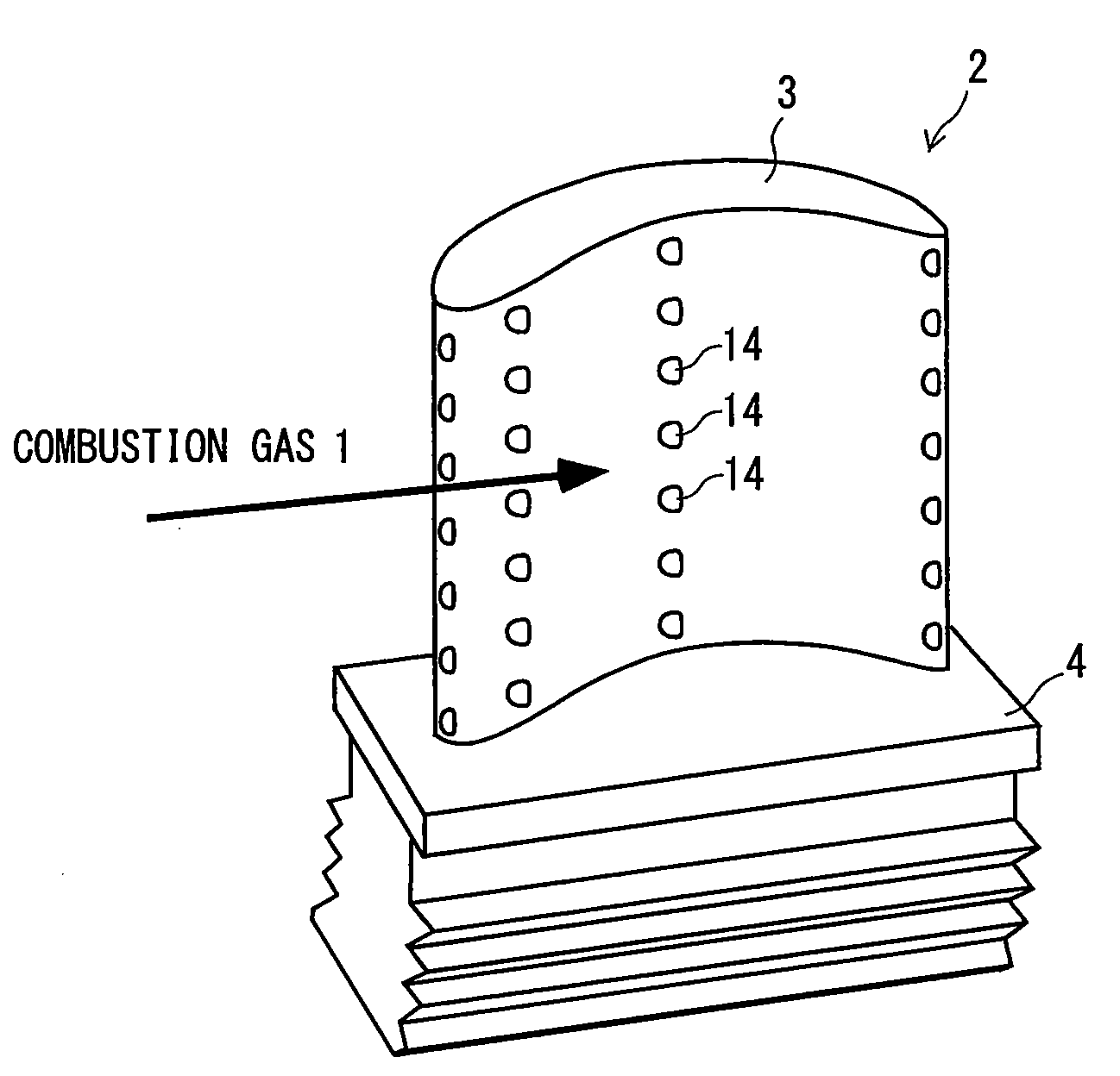
[0037]A film cooling structure according to the invention is applied to a component that is disposed on a flow passage for combustion gas in a gas turbine engine. Examples of this component include a combustor liner, a turbine nozzle vane, a turbine nozzle band, a turbine rotating blade, a turbine stator blade, a turbine shroud, and a turbine outlet liner.
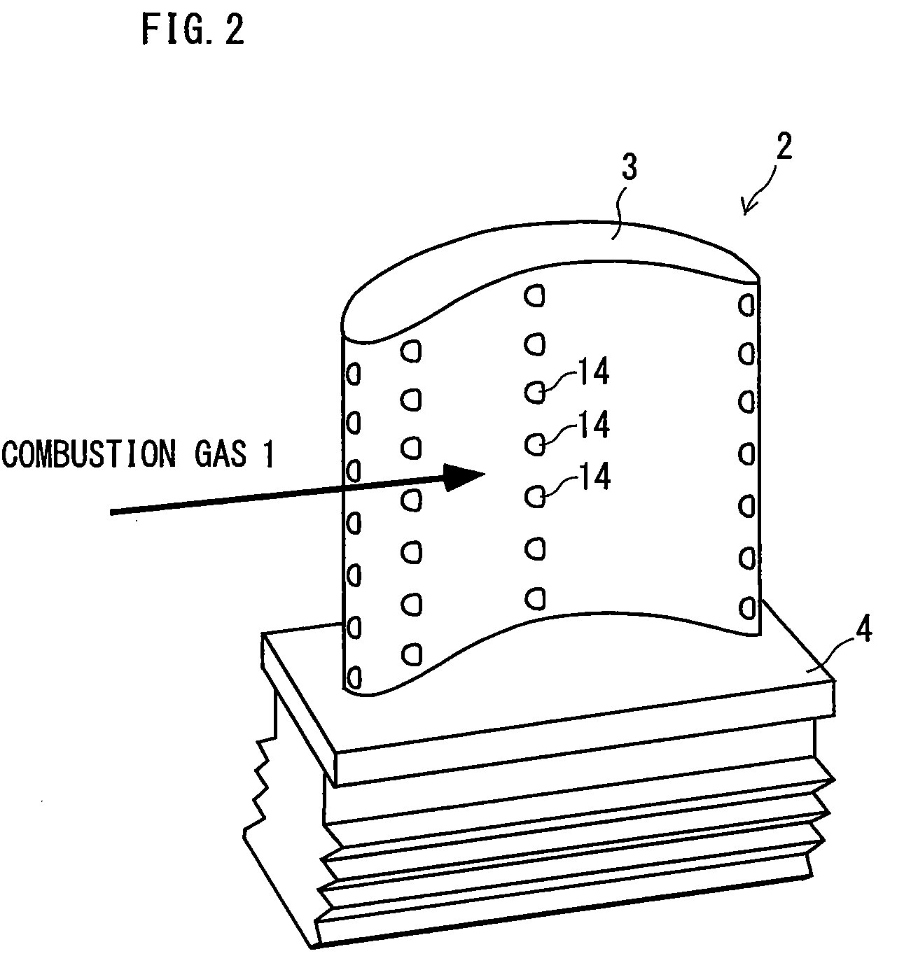
[0038]FIG. 2 is a perspective view of a turbine rotating blade 2 to which the film cooling structure 10 according to the invention is applied. The turbine rotating blade 2 includes a blade portion 3 that serves as a structural wall having an outer surface 12 exposed to combustion gas 1, and a base portion 4 that is used to mount the blade portion 3 on a rotor of an engine. A cooli...
PUM
 Abstract
Description
Claims
Application Information